Datasheet
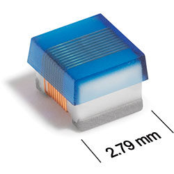
3D Model
AE413RAA Series
Outgassing Compliant Chip Inductors
AE413RAA Series offers 28 inductance values from 10 nH to 1 µH.
- High SRF and excellent Q values.
- Tight tolerances, many values at 1%.
- All parts are qualified and compliant with MIL-STD-981 Family 50, Class S.
- Tin-Lead (63/37) over tin over nickel over silver-platinum-glass-frit. Other terminations are also available.
Specifications
Electrical specifications at 25°C.
| Part number 1 | Inductance (nH) 2 | Tolerance (%) | Q min 3 | SRF min (MHz) 4 | DCR max (Ω) 5 | Imax (mA) |
|---|---|---|---|---|---|---|
| AE413RAA100_PZ | 10 @ 50.0 MHz | 5,2 | 44 @ 500 MHz | 3060 | 0.08 | 900 |
| AE413RAA120_PZ | 12 @ 50.0 MHz | 5,2 | 45 @ 500 MHz | 2680 | 0.09 | 900 |
| AE413RAA150_PZ | 15 @ 50.0 MHz | 5,2 | 50 @ 500 MHz | 2220 | 0.10 | 850 |
| AE413RAA180_PZ | 18 @ 50.0 MHz | 5,2,1 | 50 @ 350 MHz | 2200 | 0.11 | 900 |
| AE413RAA220_PZ | 22 @ 50.0 MHz | 5,2,1 | 55 @ 350 MHz | 2100 | 0.12 | 900 |
| AE413RAA270_PZ | 27 @ 50.0 MHz | 5,2,1 | 55 @ 350 MHz | 1380 | 0.13 | 900 |
| AE413RAA330_PZ | 33 @ 50.0 MHz | 5,2,1 | 60 @ 350 MHz | 1600 | 0.14 | 850 |
| AE413RAA390_PZ | 39 @ 50.0 MHz | 5,2,1 | 60 @ 350 MHz | 1420 | 0.15 | 850 |
| AE413RAA470_PZ | 47 @ 50.0 MHz | 5,2,1 | 65 @ 350 MHz | 1420 | 0.16 | 820 |
| AE413RAA560_PZ | 56 @ 50.0 MHz | 5,2,1 | 60 @ 350 MHz | 1140 | 0.18 | 780 |
| AE413RAA680_PZ | 68 @ 50.0 MHz | 5,2,1 | 46 @ 100 MHz | 1140 | 0.20 | 710 |
| AE413RAA820_PZ | 82 @ 50.0 MHz | 5,2,1 | 48 @ 100 MHz | 940 | 0.22 | 710 |
| AE413RAA101_PZ | 100 @ 25.0 MHz | 5,2,1 | 37 @ 100 MHz | 900 | 0.56 | 440 |
| AE413RAA121_PZ | 120 @ 25.0 MHz | 5,2,1 | 40 @ 100 MHz | 840 | 0.63 | 410 |
| AE413RAA151_PZ | 150 @ 25.0 MHz | 5,2,1 | 40 @ 100 MHz | 740 | 0.70 | 400 |
| AE413RAA181_PZ | 180 @ 25.0 MHz | 5,2,1 | 38 @ 100 MHz | 680 | 0.77 | 390 |
| AE413RAA221_PZ | 220 @ 25.0 MHz | 5,2,1 | 40 @ 100 MHz | 580 | 0.84 | 370 |
| AE413RAA271_PZ | 270 @ 25.0 MHz | 5,2,1 | 45 @ 100 MHz | 540 | 0.91 | 330 |
| AE413RAA331_PZ | 330 @ 25.0 MHz | 5,2,1 | 45 @ 100 MHz | 500 | 1.05 | 330 |
| AE413RAA391_PZ | 390 @ 25.0 MHz | 5,2,1 | 45 @ 100 MHz | 480 | 1.12 | 310 |
| AE413RAA471_PZ | 470 @ 25.0 MHz | 5,2,1 | 45 @ 100 MHz | 400 | 1.19 | 280 |
| AE413RAA561_PZ | 560 @ 25.0 MHz | 5,2,1 | 40 @ 100 MHz | 360 | 1.33 | 280 |
| AE413RAA621_PZ | 620 @ 25.0 MHz | 5,2,1 | 45 @ 100 MHz | 360 | 1.40 | 270 |
| AE413RAA681_PZ | 680 @ 25.0 MHz | 5,2,1 | 45 @ 100 MHz | 345 | 1.47 | 270 |
| AE413RAA751_PZ | 750 @ 25.0 MHz | 5,2,1 | 45 @ 100 MHz | 335 | 1.54 | 270 |
| AE413RAA821_PZ | 820 @ 25.0 MHz | 5,2,1 | 45 @ 100 MHz | 310 | 1.61 | 250 |
| AE413RAA911_PZ | 910 @ 25.0 MHz | 5,2,1 | 35 @ 50.0 MHz | 280 | 1.68 | 250 |
| AE413RAA102_PZ | 1000 @ 25.0 MHz | 5,2,1 | 34 @ 50.0 MHz | 280 | 1.75 | 230 |
Notes
- When ordering, specify tolerance, termination and screening codes: e.g. AE413RAA102GPZ.
- Inductance measured using a Coilcraft SMD-A fixture in an Agilent/ HP 4286A impedance analyzer or equivalent with Coilcraft-provided correlation pieces.
- Q measured using an Agilent/HP 4291A with an Agilent/HP 16197A test fixture or equivalents.
- SRF measured using an Aglilent/HP 8753ES network analyzer or equivalent and a Coilcraft CCF1297 test fixture.
- DCR measured on a Keithley 580 micro-ohmmeter or equivalent and a Coilcraft CCF858 test fixture.
Tolerance:
- F = 1%
- G = 2%
- J = 5%
Termination:
- P = Tin-lead (63/37) over tin over nickel over silverplatinum-glass frit.
- C = Tin-lead (63/37) over gold over nickel over moly-mag.
- S = Tin-lead (63/37) over leach-resistant silver-platinumglass frit.
- A = Gold over nickel over moly-mag.
- L = Silver-palladium-platinum-glass frit.
Screening:
- Z = Unscreened
- H = Coilcraft CP-SA-10001 Group A
- 1 = EEE-INST-002 (Family 3) Level 1
- 2 = EEE-INST-002 (Family 3) Level 2
- 3 = EEE-INST-002 (Family 3) Level 3
- 4 = MIL-STD-981 (Family 50) Class B
- 5 = MIL-STD-981 (Family 50) Class S
- Screening performed to the document’s latest revision.
- Lot qualification (Group B) available.
- Testing T and U have been replaced with more detailed codes 4, 5, and 1, 2, 3, respectively. Codes T and U can still be used, if necessary. Custom testing also available.
- Country of origin restrictions available; prefix options G or F.
Environmental
Ambient temperature range:
–55°C to +125°C with Imax current
Storage temperature range:
Component: –55°C to +155°C
Tape and reel packaging: –55°C to +80°C
Tape and reel packaging: –55°C to +80°C
Maximum part temperature:
+155°C (ambient + temp rise)
Failures in Time (FIT) / Mean Time Between Failures (MTBF):
Performance curves
L vs Frequency

Q vs Frequency


General specification
Core Material:
Ceramic
Packaging:
2000 per 7″ reel Plastic tape: 8 mm wide, 0.3 mm thick, 4 mm pocket spacing, 2.0 mm pocket depth.
Temperature coefficient of inductance:
+25 to +155 ppm/°C
Soldering/Washing
Moisture Sensitivity Level (MSL):
1 (unlimited floor life at <30°C / 85% relative humidity)
Resistance to soldering heat:
Max three 40 second reflows at +260°C, parts cooled to room temperature between cycles.
Refer to Soldering Coilcraft Components before soldering.