Datasheet
3D Model
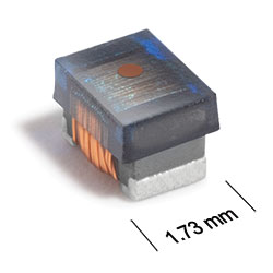
ML336RAM Series
High-Reliability Chip Inductors
The ML336RAM Series is not recommended for new designs, but existing customers will continue to be supported. As an alternative, we recommend the AR336RAM Series which is a drop-in replacement.
ML336RAM Series features higher inductance values than ceramic 0805 inductors.
- Heavy gauge wire for low DCR.
- Ferrite construction for high current handling.
- Matte tin over nickel silver-platinum-glass frit terminations.
Specifications
Electrical specifications at 25°C.
| Part number |
Inductance (µH)
1
(Tolerance: ±5%) |
Impedance typ (Ω) | Q min 2 | SRF min (MHz) 3 | DCR max (Ω) 4 | Imax (mA) | Color code |
|---|---|---|---|---|---|---|---|
| ML336RAM111JRZ | 0.11 @ 7.9 MHz | 370 @ 500 MHz | 14 @ 7.9 MHz | 1000 | 0.05 | 700 | Brown |
| ML336RAM681JRZ | 0.68 @ 7.9 MHz | 430 @ 100 MHz | 15 @ 7.9 MHz | 340 | 0.3 | 410 | Orange |
| ML336RAM102JRZ | 1.0 @ 7.9 MHz | 670 @ 100 MHz | 13 @ 7.9 MHz | 280 | 0.39 | 360 | Yellow |
| ML336RAM122JRZ | 1.2 @ 7.9 MHz | 860 @ 100 MHz | 15 @ 7.9 MHz | 300 | 0.64 | 260 | Brown |
| ML336RAM152JRZ | 1.5 @ 7.9 MHz | 1000 @ 100 MHz | 16 @ 7.9 MHz | 225 | 0.74 | 250 | Green |
| ML336RAM182JRZ | 1.8 @ 7.9 MHz | 1360 @ 100 MHz | 16 @ 7.9 MHz | 240 | 0.98 | 210 | Blue |
| ML336RAM222JRZ | 2.2 @ 7.9 MHz | 840 @ 50.0 MHz | 15 @ 7.9 MHz | 90.0 | 0.98 | 190 | Brown |
| ML336RAM272JRZ | 2.7 @ 7.9 MHz | 1050 @ 50.0 MHz | 15 @ 7.9 MHz | 80.0 | 1.16 | 190 | Violet |
| ML336RAM332JRZ | 3.3 @ 7.9 MHz | 1670 @ 50.0 MHz | 15 @ 7.9 MHz | 65.0 | 1.2 | 190 | Gray |
| ML336RAM472JRZ | 4.7 @ 7.9 MHz | 950 @ 25.0 MHz | 14 @ 7.9 MHz | 40.0 | 1.5 | 170 | Black |
| ML336RAM682JRZ | 6.8 @ 7.9 MHz | 450 @ 10.0 MHz | 14 @ 7.9 MHz | 28.0 | 1.9 | 150 | Brown |
| ML336RAM103JRZ | 10 @ 2.5 MHz | 740 @ 10.0 MHz | 14 @ 2.5 MHz | 18.0 | 2.2 | 130 | Red |
| ML336RAM153JRZ | 15 @ 2.5 MHz | 1300 @ 10.0 MHz | 13 @ 2.5 MHz | 15.0 | 4.25 | 90 | Yellow |
| ML336RAM223JRZ | 22 @ 2.5 MHz | 1620 @ 10.0 MHz | 13 @ 2.5 MHz | 15.0 | 6.7 | 75 | Green |
Notes
- Inductance measured at 0.1 Vrms, using Coilcraft SMD-A fixture in Agilent/HP 4286A impedance analyzer or equivalent with Coilcraftprovided correlation pieces.
- Q measured on Agilent/HP 4291A with Agilent/HP 16197A test fixture or equivalents.
- SRF measured using Agilent/HP 8753ES network analyzer or equivalent with Coilcraft CCF1297 test fixture.
- DCR measured on a Keithley 580 Micro-ohmmeter or equivalent with a Coilcraft CCF858 test fixture.
Environmental
Ambient temperature range:
–55°C to +125°C with Imax current.
Storage temperature range:
Component: –55°C to +155°C.
Packaging: –55°C to +80°C.
Packaging: –55°C to +80°C.
Maximum part temperature:
+155°C (ambient + temp rise).
Failures in Time (FIT) / Mean Time Between Failures (MTBF):
Performance curves
Impedance vs Frequency

L vs Frequency

Q vs Frequency

Physical characteristics

| A max | B max | C max | D ref | E | F | G | H | I | J | |
|---|---|---|---|---|---|---|---|---|---|---|
| 0.090 | 0.068 | 0.060 | 0.020 | 0.050 | 0.016 | 0.040 | 0.070 | 0.040 | 0.030 | inches |
| 2,29 | 1,73 | 1,52 | 0,51 | 1,27 | 0,41 | 1,02 | 1,78 | 1,02 | 0,76 | mm |
General specification
Core Material:
Ferrite
Weight:
16.7– 18.0 mg
Packaging:
2000/7″reel; Plastic tape: 8 mm wide, 0.23 mm thick, 4 mm pocket spacing, 1.6 mm pocket depth.
Soldering/Washing
Moisture Sensitivity Level (MSL):
1 (unlimited floor life at <30°C / 85% relative humidity).
Resistance to soldering heat:
Max three 40 second reflows at +260°C, parts cooled to room temperature between cycles.
Refer to Soldering Coilcraft Components before soldering.