Datasheet
3D Model
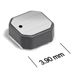
MS425PJB Series
High-Reliability Power Inductors
MS425PJB Series offers high temperature materials allowing operation in ambient temperatures up to 155°C.
- Special construction allows it to pass vibration testing to 80 G and shock testing to 1000 G.
- Tin-lead (Sn-Pb) termination for the best possible board adhesion.
- Tin-lead (63/37) over tin over nickel terminations.
Specifications
Electrical specifications at 25°C.
| Part number 1 | Inductance (µH) 2 | Tolerance (%) | DCR max (Ω) 3 | SRF (MHz) 4 | Isat (A) 5 | Irms (A) 6 | ||||
|---|---|---|---|---|---|---|---|---|---|---|
| min | typ | 10% drop | 20% drop | 30% drop | 20°C rise | 40°C rise | ||||
| MS425PJB351MSZ | 0.35 | 20 | 0.040 | 252 | 360 | 5.9 | 6.1 | 6.3 | 2.2 | 3.1 |
| MS425PJB561MSZ | 0.56 | 20 | 0.030 | 175 | 250 | 4.8 | 5.2 | 5.3 | 1.9 | 2.8 |
| MS425PJB102NSZ | 1.0 | 30 | 0.040 | 126 | 180 | 2.8 | 3.0 | 3.1 | 1.8 | 2.7 |
| MS425PJB222MSZ | 2.2 | 20 | 0.070 | 63.0 | 90.0 | 2.7 | 2.8 | 2.9 | 1.6 | 2.3 |
| MS425PJB262MSZ | 2.6 | 20 | 0.080 | 59.0 | 85.0 | 2.6 | 2.7 | 2.8 | 1.5 | 2.0 |
| MS425PJB332MSZ | 3.3 | 20 | 0.080 | 52.0 | 75.0 | 2.1 | 2.3 | 2.4 | 1.4 | 2.0 |
| MS425PJB472MSZ | 4.7 | 20 | 0.13 | 45.0 | 65.0 | 1.8 | 1.9 | 1.9 | 1.3 | 1.8 |
| MS425PJB682MSZ | 6.8 | 20 | 0.15 | 35.0 | 50.0 | 1.2 | 1.3 | 1.3 | 1.0 | 1.5 |
| MS425PJB103MSZ | 10 | 20 | 0.20 | 28.0 | 40.0 | 1.1 | 1.2 | 1.3 | 0.90 | 1.3 |
| MS425PJB153MSZ | 15 | 20 | 0.26 | 22.0 | 32.0 | 0.86 | 0.91 | 0.94 | 0.80 | 1.1 |
| MS425PJB183MSZ | 18 | 20 | 0.27 | 18.0 | 27.0 | 0.78 | 0.83 | 0.85 | 0.70 | 1.0 |
| MS425PJB223MSZ | 22 | 20 | 0.36 | 18.0 | 26.0 | 0.74 | 0.80 | 0.83 | 0.65 | 0.90 |
| MS425PJB333MSZ | 33 | 20 | 0.42 | 14.0 | 20.0 | 0.58 | 0.64 | 0.68 | 0.55 | 0.80 |
| MS425PJB473MSZ | 47 | 20 | 0.65 | 11.0 | 16.0 | 0.51 | 0.55 | 0.56 | 0.45 | 0.68 |
| MS425PJB683MSZ | 68 | 20 | 0.95 | 9.0 | 13.0 | 0.41 | 0.45 | 0.46 | 0.40 | 0.56 |
| MS425PJB104MSZ | 100 | 20 | 1.4 | 7.0 | 10.0 | 0.34 | 0.36 | 0.37 | 0.35 | 0.50 |
| MS425PJB124MSZ | 120 | 20 | 1.6 | 6.0 | 9.0 | 0.31 | 0.33 | 0.34 | 0.30 | 0.45 |
| MS425PJB154MSZ | 150 | 20 | 2.0 | 5.6 | 8.0 | 0.27 | 0.29 | 0.30 | 0.28 | 0.40 |
| MS425PJB184MSZ | 180 | 20 | 2.5 | 5.2 | 7.5 | 0.24 | 0.26 | 0.27 | 0.26 | 0.36 |
| MS425PJB224MSZ | 220 | 20 | 3.7 | 4.5 | 6.5 | 0.21 | 0.23 | 0.24 | 0.20 | 0.30 |
| MS425PJB334MSZ | 330 | 20 | 5.9 | 3.8 | 5.5 | 0.18 | 0.19 | 0.20 | 0.17 | 0.23 |
| MS425PJB474MSZ | 470 | 20 | 7.8 | 3.0 | 4.5 | 0.14 | 0.16 | 0.17 | 0.15 | 0.20 |
| MS425PJB564MSZ | 560 | 20 | 10.0 | 2.8 | 4.0 | 0.13 | 0.14 | 0.15 | 0.14 | 0.18 |
| MS425PJB684MSZ | 680 | 20 | 11.5 | 2.4 | 3.5 | 0.12 | 0.13 | 0.14 | 0.12 | 0.16 |
| MS425PJB824MSZ | 820 | 20 | 14.0 | 2.0 | 2.9 | 0.11 | 0.12 | 0.13 | 0.10 | 0.14 |
| MS425PJB105MSZ | 1000 | 20 | 18.0 | 1.9 | 2.8 | 0.10 | 0.11 | 0.11 | 0.098 | 0.13 |
| MS425PJB155MSZ | 1500 | 20 | 25.0 | 1.6 | 2.4 | 0.095 | 0.10 | 0.11 | 0.080 | 0.11 |
| MS425PJB185MSZ | 1800 | 20 | 31.5 | 1.6 | 2.3 | 0.090 | 0.095 | 0.10 | 0.070 | 0.095 |
| MS425PJB225MSZ | 2200 | 20 | 32.5 | 1.4 | 2.1 | 0.088 | 0.099 | 0.10 | 0.070 | 0.090 |
| MS425PJB335MSZ | 3300 | 20 | 48.0 | 1.1 | 1.6 | 0.082 | 0.092 | 0.094 | 0.055 | 0.075 |
Notes
- When ordering, please specify screening code: MS425PJB335MSZ.
- Inductance tested at 100 kHz, 0.1 Vrms using an Agilent/HP 4192A. Inductance at 1 MHz is the same for parts with SRF ≥10 MHz.
- DCR measured on a micro-ohmmeter.
- SRF measured using Agilent/HP 8753ES or equivalent.
- DC current at 25°C that causes the specified inductance drop from its value without current.
- Current that causes the specified temperature rise from 25°C ambient. This information is for reference only and does not represent absolute maximum ratings.
Screening:
- Z = Unscreened
- Y = Unscreened (SLDC Option A)
- W = Unscreened (SLDC Option B)
- H = Coilcraft CP-SA-10001Group A
- G = Coilcraft CP-SA-10001 Group A (SLDC Option B)
- D = Coilcraft CP-SA-10001 Group A (SLDC Option B)
- 1 = EEE-INST-002 (Family 1) Level 1
- 2 = EEE-INST-002 (Family 1) Level 2
- 3 = EEE-INST-002 (Family 1) Level 3
- 4 = MIL-STD-981 (Family 04) Class B
- 5 = MIL-STD-981 (Family 04) Class S
- F = ESCC3201 (F4 operational life performed at 105°C)
- Screening performed to the document’s latest revision.
- Lot qualification (Group B) available.
- Testing T and U have been replaced with more detailed codes 4, 5, and 1, 2, 3, respectively. Codes T and U can still be used, if necessary. Custom testing also available.
- Country of origin restrictions available; prefix options G or F.
Environmental
Ambient temperature range:
–55°C to +105°C with Irms current.
Storage temperature range:
Component: –55°C to +155°C.
Packaging: –55°C to +80°C.
Packaging: –55°C to +80°C.
Maximum part temperature:
+155°C (ambient + temp rise).
Failures in Time (FIT) / Mean Time Between Failures (MTBF):
Performance curves
L vs Frequency

L vs Current

.png "ms425pjb_dim-(2).png")
General specification
Core Material:
Ferrite
Weight:
104 – 120 mg
Packaging:
1000/7″ reel Plastic tape: 12 mm wide, 0.23 mm thick, 8 mm pocket spacing, 1.9 mm pocket depth.
Soldering/Washing
Moisture Sensitivity Level (MSL):
1 (unlimited floor life at <30°C / 85% relative humidity).
Resistance to soldering heat:
Max three 40 second reflows at +260°C, parts cooled to room temperature between cycles.
Refer to Soldering Coilcraft Components before soldering.
Recommended Pick & Place Nozzle:
OD: 4 mm; ID: ≤ 2 mm.