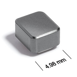
ST450PHA Series
Power Inductor for Critical Applications
ST450PHA Series features high inductance with tight tolerance.
- Shielded power inductors.
- Excellent current handling for a part this size; low DCR.
- Silver-palladium-platinum-glass frit. Other terminations available at additional cost.
Specifications
Electrical specifications at 25°C.
| Part number 1 |
Inductance (µH)
2
(Tolerance: ±10%) |
DCR max (Ω) 3 | SRF typ (MHz) 4 | Isat (A) 5 | Irms (A) 6 |
|---|---|---|---|---|---|
| ST450PHA102KLZ | 1.0 | 0.05 | 685 | 2.50 | 2.70 |
| ST450PHA122KLZ | 1.2 | 0.06 | 460 | 2.00 | 2.60 |
| ST450PHA152KLZ | 1.5 | 0.06 | 460 | 2.00 | 2.60 |
| ST450PHA222KLZ | 2.2 | 0.07 | 270 | 1.70 | 2.40 |
| ST450PHA272KLZ | 2.7 | 0.08 | 265 | 1.40 | 2.30 |
| ST450PHA332KLZ | 3.3 | 0.09 | 225 | 1.40 | 2.30 |
| ST450PHA392KLZ | 3.9 | 0.11 | 170 | 1.20 | 2.20 |
| ST450PHA472KLZ | 4.7 | 0.11 | 165 | 1.15 | 2.10 |
| ST450PHA562KLZ | 5.6 | 0.12 | 155 | 1.10 | 2.10 |
| ST450PHA682KLZ | 6.8 | 0.13 | 140 | 1.00 | 1.90 |
| ST450PHA103KLZ | 10 | 0.17 | 120 | 0.90 | 1.70 |
| ST450PHA153KLZ | 15 | 0.26 | 100 | 0.70 | 1.45 |
| ST450PHA223KLZ | 22 | 0.33 | 45 | 0.54 | 1.20 |
| ST450PHA333KLZ | 33 | 0.40 | 30 | 0.46 | 1.10 |
| ST450PHA393KLZ | 39 | 0.56 | 30 | 0.40 | 1.00 |
| ST450PHA473KLZ | 47 | 0.87 | 28 | 0.35 | 0.80 |
| ST450PHA683KLZ | 68 | 1.08 | 17 | 0.32 | 0.67 |
| ST450PHA823KLZ | 82 | 1.25 | 17 | 0.28 | 0.65 |
| ST450PHA104KLZ | 100 | 1.32 | 14 | 0.27 | 0.65 |
| ST450PHA124KLZ | 120 | 1.45 | 12 | 0.23 | 0.60 |
| ST450PHA154KLZ | 150 | 2.20 | 11 | 0.20 | 0.51 |
| ST450PHA224KLZ | 220 | 2.65 | 7 | 0.17 | 0.47 |
| ST450PHA334KLZ | 330 | 4.85 | 6 | 0.15 | 0.31 |
| ST450PHA474KLZ | 470 | 5.85 | 4 | 0.12 | 0.31 |
| ST450PHA564KLZ | 560 | 6.10 | 3 | 0.11 | 0.28 |
| ST450PHA684KLZ | 680 | 6.60 | 2 | 0.10 | 0.28 |
| ST450PHA824KLZ | 820 | 7.35 | 2 | 0.09 | 0.25 |
| ST450PHA105KLZ | 1000 | 10.00 | 2 | 0.08 | 0.22 |
Notes
- When ordering, please specify termination and screening codes: e.g. ST450PHA105KLZ.
- Inductance measured at 100 kHz, 0.1 Vrms, using Coilcraft SMD-A fixture in Agilent/HP 4263B impedance analyzer or equivalent.
- DCR measured on micro-ohmmeter and a Coilcraft CCF859 test fixture.
- SRF measured using an Agilent/HP 8753D network analyzer and a Coilcraft CCF1301 test fixture.
- DC current at which the inductance drops 10% (typ) from its value without current.
- Current that causes a 40°C temperature rise from 25°C ambient. This information is for reference only and does not represent absolute maximum ratings.
Termination:
- L = Silver-palladium-platinum-glass frit terminations.
- T = Tin-silver-copper (95.5/4/0.5). (Special order, added cost)
- S = Tin-lead (63/37). (Special order, added cost)
Screening:
- Z = Unscreened
- Y = Unscreened (SLDC Option A)
- W = Unscreened (SLDC Option B)
- H = Group A screening per Coilcraft CP-SA-10001
- G= Coilcraft CP-SA-10001 Group A (SLDC Option A)
- D = Coilcraft CP-SA-10001 Group A (SLDC Option B)
Environmental
Ambient temperature range:
–40°C to +105°C with Irms current.
Storage temperature range:
Component: –55°C to +145°C.
Packaging: –55°C to +80°C.
Packaging: –55°C to +80°C.
Maximum part temperature:
+145°C (ambient + temp rise).
Failures in Time (FIT) / Mean Time Between Failures (MTBF):
Performance curves
Typical L vs Frequency

Typical L vs Current


General specification
Core Material:
Ceramic/Ferrite
Weight:
286– 323 mg
Packaging:
600 per 7″ reel Plastic tape: 12 mm wide, 0.25 mm thick, 4 mm pocket spacing.
Soldering/Washing
Moisture Sensitivity Level (MSL):
1 (unlimited floor life at <30°C / 85% relative humidity).
Resistance to soldering heat:
Max three 40 second reflows at +260°C, parts cooled to room temperature between cycles.
Refer to Soldering Coilcraft Components before soldering.