3D Model
Datasheet
AE412PJD Series
Coupled Inductors for Critical Applications
AE412PJD Series features high inductance, high efficiency and excellent current handling
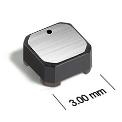
- Only 1.4 mm high and 3 mm square.
- Ideal for use in flyback, multi-output buck, SEPIC and Zeta applications..
- Can also be used as two single inductors connected in series or parallel or as a common mode choke.
- Tin-lead (63/37) over tin over nickel terminations. Other terminations available at additional cost.
Specifications
Electrical specifications at 25°C.
For Flyback Applications
| Part number 1 | Inductance (µH) 2 | Tolerance (%) | DCR max (Ω) 3 |
Isolation Voltage (V) |
Leakage Inductance (µH) 5 |
|---|---|---|---|---|---|
| AE412PJD391NPZ | 0.39 | 30 | 0.071 | 100 | 0.080 |
| AE412PJD561MPZ | 0.56 | 20 | 0.079 | 100 | 0.080 |
| AE412PJD102MPZ | 1.0 | 20 | 0.13 | 100 | 0.090 |
| AE412PJD152MPZ | 1.5 | 20 | 0.20 | 100 | 0.11 |
| AE412PJD182MPZ | 1.8 | 20 | 0.27 | 100 | 0.13 |
| AE412PJD222MPZ | 2.2 | 20 | 0.30 | 100 | 0.14 |
| AE412PJD332MPZ | 3.3 | 20 | 0.34 | 100 | 0.16 |
| AE412PJD472MPZ | 4.7 | 20 | 0.50 | 100 | 0.18 |
| AE412PJD682MPZ | 6.8 | 20 | 0.62 | 100 | 0.22 |
| AE412PJD103MPZ | 10 | 20 | 1.0 | 100 | 0.28 |
| AE412PJD153MPZ | 15 | 20 | 1.4 | 100 | 0.37 |
| AE412PJD183MPZ | 18 | 20 | 1.6 | 100 | 0.42 |
| AE412PJD223MPZ | 22 | 20 | 1.9 | 100 | 0.48 |
| AE412PJD333MPZ | 33 | 20 | 2.8 | 100 | 0.63 |
| AE412PJD473MPZ | 47 | 20 | 4.0 | 100 | 0.81 |
| AE412PJD683MPZ | 68 | 20 | 6.1 | 100 | 1.1 |
| AE412PJD104MPZ | 100 | 20 | 8.5 | 100 | 1.5 |
| AE412PJD124MPZ | 120 | 20 | 9.2 | 100 | 1.8 |
| AE412PJD154MPZ | 150 | 20 | 12.4 | 100 | 2.2 |
| AE412PJD184MPZ | 180 | 20 | 15.3 | 100 | 2.8 |
| AE412PJD224MPZ | 220 | 20 | 18.6 | 100 | 3.6 |
| AE412PJD334MPZ | 330 | 20 | 27.7 | 100 | 5.2 |
For SEPIC Applications
| Part number 1 | Inductance (µH) 2 | Tolerance (%) | DCR max (Ω) 3 | SRF Typ (MHz) 4 | Coupling coefficient |
Leakage Inductance (µH) 5 |
Isat (A) 6 | Irms (A) | |||
|---|---|---|---|---|---|---|---|---|---|---|---|
| 10% drop | 20% drop | 30% drop | both windings 7 | one winding 8 | |||||||
| AE412PJD391NPZ | 0.39 | 30 | 0.071 | 289 | 0.89 | 0.080 | 3.2 | 3.3 | 3.4 | 1.45 | 2.05 |
| AE412PJD561MPZ | 0.56 | 20 | 0.079 | 235 | 0.93 | 0.080 | 2.7 | 2.8 | 2.8 | 1.37 | 1.94 |
| AE412PJD102MPZ | 1.0 | 20 | 0.13 | 160 | 0.95 | 0.090 | 2.0 | 2.1 | 2.2 | 1.08 | 1.52 |
| AE412PJD152MPZ | 1.5 | 20 | 0.20 | 140 | 0.96 | 0.11 | 1.6 | 1.7 | 1.8 | 0.86 | 1.20 |
| AE412PJD182MPZ | 1.8 | 20 | 0.27 | 135 | 0.96 | 0.13 | 1.5 | 1.6 | 1.6 | 0.78 | 1.10 |
| AE412PJD222MPZ | 2.2 | 20 | 0.30 | 110 | 0.97 | 0.14 | 1.5 | 1.6 | 1.6 | 0.75 | 1.05 |
| AE412PJD332MPZ | 3.3 | 20 | 0.34 | 90.0 | 0.98 | 0.16 | 1.0 | 1.1 | 1.2 | 0.67 | 0.94 |
| AE412PJD472MPZ | 4.7 | 20 | 0.50 | 79.0 | 0.98 | 0.18 | 0.86 | 0.87 | 0.88 | 0.54 | 0.76 |
| AE412PJD682MPZ | 6.8 | 20 | 0.62 | 58.0 | 0.98 | 0.22 | 0.77 | 0.78 | 0.79 | 0.49 | 0.69 |
| AE412PJD103MPZ | 10 | 20 | 1.0 | 48.0 | 0.99 | 0.28 | 0.58 | 0.59 | 0.60 | 0.38 | 0.53 |
| AE412PJD153MPZ | 15 | 20 | 1.4 | 35.0 | 0.99 | 0.37 | 0.49 | 0.50 | 0.51 | 0.32 | 0.46 |
| AE412PJD183MPZ | 18 | 20 | 1.6 | 33.0 | 0.99 | 0.42 | 0.46 | 0.47 | 0.48 | 0.31 | 0.44 |
| AE412PJD223MPZ | 22 | 20 | 1.9 | 30.0 | 0.99 | 0.48 | 0.42 | 0.43 | 0.44 | 0.28 | 0.40 |
| AE412PJD333MPZ | 33 | 20 | 2.8 | 23.0 | 0.99 | 0.63 | 0.34 | 0.35 | 0.36 | 0.23 | 0.32 |
| AE412PJD473MPZ | 47 | 20 | 4.0 | 17.0 | 0.99 | 0.81 | 0.28 | 0.29 | 0.30 | 0.19 | 0.27 |
| AE412PJD683MPZ | 68 | 20 | 6.1 | 14.0 | 0.99 | 1.1 | 0.24 | 0.25 | 0.26 | 0.16 | 0.22 |
| AE412PJD104MPZ | 100 | 20 | 8.5 | 11.0 | 0.99 | 1.5 | 0.20 | 0.21 | 0.22 | 0.13 | 0.19 |
| AE412PJD124MPZ | 120 | 20 | 9.2 | 9.0 | 0.99 | 1.8 | 0.19 | 0.20 | 0.20 | 0.13 | 0.18 |
| AE412PJD154MPZ | 150 | 20 | 12.4 | 8.0 | 0.99 | 2.2 | 0.16 | 0.17 | 0.18 | 0.11 | 0.16 |
| AE412PJD184MPZ | 180 | 20 | 15.3 | 7.5 | 0.99 | 2.8 | 0.15 | 0.16 | 0.17 | 0.10 | 0.14 |
| AE412PJD224MPZ | 220 | 20 | 18.6 | 6.0 | 0.99 | 3.6 | 0.13 | 0.14 | 0.15 | 0.09 | 0.13 |
| AE412PJD334MPZ | 330 | 20 | 27.7 | 5.0 | 0.99 | 5.2 | 0.11 | 0.12 | 0.12 | 0.07 | 0.10 |
Notes
- When ordering, please specify termination and screening codes: e.g. AE412PJD334MPZ.
- Inductance shown for each winding, measured at 100 kHz, 0.1 Vrms, 0 Adc on an Agilent/HP 4284A LCR meter or equivalent. When leads are connected in parallel, inductance is the same value. When leads are connected in series, inductance is four times the value.
- DCR is for each winding. When leads are connected in parallel, DCR is half the value. When leads are connected in series, DCR is twice the value.
- SRF measured using an Agilent/HP 4191A or equivalent. When leads are connected in parallel, SRF is the same value.
- Leakage Inductance is for L1 and is measured with L2 shorted.
- DC current at 25°C that causes the specified inductance drop from its value without current. It is the sum of the current flowing in both windings.
- Equal current when applied to each winding simultaneously that causes a 40°C temperature rise from 25°C ambient. This information is for reference only and does not represent absolute maximum ratings.
- Maximum current when applied to one winding that causes a 40°C temperature rise from 25°C ambient. This information is for reference only and does not represent absolute maximum ratings.
Coupled Inductor Core and Winding Loss Calculator
This web-based utility allows you to enter frequency, peak-to-peak (ripple) current, and Irms current to predict temperature rise and overall losses, including core loss.
Refer to Doc 639 “Selecting Coupled Inductors for SEPIC Applications.”
This web-based utility allows you to enter frequency, peak-to-peak (ripple) current, and Irms current to predict temperature rise and overall losses, including core loss.
Refer to Doc 639 “Selecting Coupled Inductors for SEPIC Applications.”
Termination:
- P = Tin-lead (63/37) over tin over nickel.
- R = Matte tin over nickel over silver-platinum glass frit.
- Q = Tin-silver-copper (95.5/4/0.5) over tin over nickel over silver-platinum-glass frit.
Screening:
- Z = Unscreened
- Y = Unscreened (SLDC Option A)
- W = Unscreened (SLDC Option B)
- H = Coilcraft CP-SA-10001 Group A
- G = Coilcraft CP-SA-10001 Group A (SLDC Option A)
- D = Coilcraft CP-SA-10001 Group A (SLDC Option B)
- 1 = EEE-INST-002 (Family 1) Level 1
- 2 = EEE-INST-002 (Family 1) Level 2
- 3 = EEE-INST-002 (Family 1) Level 3
- 4 = MIL-STD-981 (Family 04) Class B
- 5 = MIL-STD-981 (Family 04) Class S
- F = ESCC3201 (F4 operational life performed at 105°C)
- Screening performed to the document’s latest revision.
- Lot qualification (Group B) available.
- Testing T and U have been replaced with more detailed codes 4, 5, and 1, 2, 3, respectively. Codes T and U can still be used, if necessary. Custom testing also available.
- Country of origin restrictions available; prefix options G or F.
Environmental
Ambient temperature range:
–55°C to +105°C with Irms current.
Storage temperature range:
Component: –55°C to +155°C.
Packaging: –55°C to +80°C.
Packaging: –55°C to +80°C.
Maximum part temperature:
+155°C (ambient + temp rise).
Failures in Time (FIT) / Mean Time Between Failures (MTBF):
Performance curves
Typical L vs Current

Typical L vs Frequency
.gif "Typical L vs Frequency")
Schematics


General specification
Core Material:
Ferrite
Weight:
48 – 66 mg
Packaging:
1000/7′′ reel Plastic tape: 12 mm wide, 0.26 mm thick, 8 mm pocket spacing, 1.65 mm pocket depth.
Winding to Winding Isolation:
100 V
Soldering/Washing
Moisture Sensitivity Level (MSL):
1 (unlimited floor life at <30°C / 85% relative humidity).
Resistance to soldering heat:
Max three 40 second reflows at +260°C, parts cooled to room temperature between cycles.
Refer to Soldering Coilcraft Components before soldering.
Recommended Pick & Place Nozzle:
OD: 3 mm; ID: ≤ 1.5 mm