Datasheet
3D Model
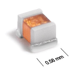
ST145RAP Series
Ceramic Chip Inductors
The ST145RAP Series has high inductance values, with twice the Q factor of thin-film technology inductors of the same size. Measuring just 0.58 x 0.46 x 0.46 mm, they are optimized for LTE Antenna matching.
- Higher L than other 0201 inductors.
- Twice the Q of thin-film multilayer technology.
- Optimized for LTE Antenna matching.
- Tin over nickel over moly-mag terminations.
Specifications
Electrical specifications at 25°C.
| Part number 1 |
Inductance (nH)
2
(Tolerance: ± 5%) |
900 MHz | 1.7 GHz | 2.4 GHz |
Q min
@ 250 MHz 3 |
SRF min (GHz) 4 | DCR max (Ω) 5 | Imax (mA) | |||
|---|---|---|---|---|---|---|---|---|---|---|---|
| L typ | Q typ 3 | L typ | Q typ 3 | L typ | Q typ 3 | ||||||
| ST145RAP22NXJRZ | 22 | 21.8 | 36 | 22.7 | 52 | 24.2 | 62 | 14 | 3.50 | 0.75 | 140 |
| ST145RAP24NXJRZ | 24 | 23.8 | 36 | 24.9 | 53 | 27.1 | 56 | 14 | 3.50 | 0.93 | 130 |
| ST145RAP27NXJRZ | 27 | 26.9 | 35 | 28.2 | 47 | 30.5 | 55 | 14 | 3.20 | 1.03 | 125 |
| ST145RAP33NXJRZ | 33 | 33 | 35 | 35.4 | 45 | 39.6 | 49 | 14 | 3.00 | 1.14 | 120 |
| ST145RAP39NXJRZ | 39 | 39.4 | 35 | 42.7 | 43 | 49.5 | 45 | 14 | 2.75 | 1.55 | 100 |
| ST145RAP47NXJRZ | 47 | 47.6 | 35 | 52.8 | 43 | 64.3 | 41 | 14 | 2.60 | 1.70 | 95 |
| ST145RAP51NXJRZ | 51 | 51.9 | 35 | 58.3 | 44 | 71.5 | 44 | 14 | 2.75 | 1.85 | 90 |
Notes
- When ordering, please specify termination and screening codes: e.g. ST145RAP51NJRZ.
- Inductance measured at 250 MHz using a Coilcraft SMD-F fixture in an Agilent/HP 4982 impedance analyzer with Coilcraft-provided correlation pieces.
- Q measured using an Agilent/HP 4991A with an Agilent/HP 16197 test fixture.
- SRF measured using an Agilent/HP 8722ES network analyzer and a Coilcraft CCF1235 test fixture.
- DCR measured on a micro-ohmmeter and a Coilcraft CCF1099 test fixture.
Termination:
- R=Tin over nickel over moly-mag.
- P=Tin-lead (63/37) over tin over nickel over moly-mag.
- Q=Tin-silver-copper (95.5/4/0.5) over tin over nickel over moly-mag.
Screening:
- Z = Unscreened
- H = Coilcraft CP-SA-10001 Group A
- Screening performed to the document’s latest revision.
- Lot qualification (Group B) available.
- Custom testing also available.
- Country of origin restrictions available; prefix options G or F.
Environmental
Ambient temperature range:
–40°C to +85°C with Irms current.
Storage temperature range:
Component: –55°C to +125°C.
Tape and reel packaging: –55°C to +80°C.
Tape and reel packaging: –55°C to +80°C.
Maximum part temperature:
+125°C (ambient + temp rise).
Failures in Time (FIT) / Mean Time Between Failures (MTBF):
Performance curves
Impedance vs Frequency

L vs Frequency

Q vs Frequency


General specification
Core Material:
Ceramic
Weight:
0.14 – 0.23 mg
Packaging:
2000 per 7″ reel. Paper tape: 8 mm wide, 0.68 mm thick, 2 mm pocket spacing.
Temperature coefficient of inductance:
+25 to +150 ppm/°C.
Soldering/Washing
Moisture Sensitivity Level (MSL):
1 (unlimited floor life at <30°C / 85% relative humidity).
Resistance to soldering heat:
Max three 40 second reflows at +260°C, parts cooled to room temperature between cycles.
Refer to Soldering Coilcraft Components before soldering.