Datasheet
3D Model
ST251PHJ Series
Shielded Power Inductor
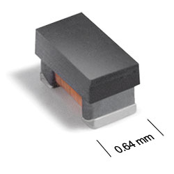
ST251PHJ Series smallest power inductor – only 0.71 mm high, 1.14 x 0.635 mm footprint.
- Handles current up to 2800 mAmps.
- RoHS compliant matte tin over nickel over silverplatinum-glass frit. Other terminations available at addiitonal cost.
Specifications
. Electrical specifications at 25°C.
| Part number 1 |
Inductance (nH)
2
(Tolerance: ±20%) |
DCR (mΩ) 3 | SRF min (MHz) 4 | Isat (mA) 5 | Irms (mA) 6 | ||||
|---|---|---|---|---|---|---|---|---|---|
| typ | max | 10% drop | 20% drop | 30% drop | 20°C rise | 40°C rise | |||
| ST251PHJ18NMRZ | 18 | 45 | 55 | 2800 | 2000 | 2500 | 2600 | 1400 | 2000 |
| ST251PHJ36NMRZ | 36 | 40 | 50 | 2100 | 1500 | 2400 | 2800 | 1400 | 2000 |
| ST251PHJ60NMRZ | 60 | 50 | 60 | 1700 | 1300 | 1900 | 2100 | 1200 | 1600 |
| ST251PHJ101MRZ | 100 | 65 | 75 | 1800 | 1000 | 1500 | 1900 | 1100 | 1500 |
| ST251PHJ181MRZ | 180 | 110 | 125 | 1000 | 700 | 880 | 1100 | 900 | 1200 |
| ST251PHJ271MRZ | 270 | 205 | 230 | 750 | 450 | 650 | 740 | 700 | 910 |
| ST251PHJ391MRZ | 390 | 490 | 540 | 650 | 380 | 510 | 550 | 450 | 570 |
| ST251PHJ561MRZ | 560 | 490 | 540 | 520 | 300 | 440 | 490 | 410 | 530 |
| ST251PHJ721MRZ | 720 | 650 | 700 | 470 | 280 | 400 | 450 | 370 | 470 |
| ST251PHJ102MRZ | 1000 | 970 | 1030 | 390 | 270 | 350 | 380 | 310 | 400 |
Notes
- When ordering, please specify termination and screening codes: e.g. ST251PHJ102MRZ.
- Inductance tested at 7.9 MHz, 0.1 Vrms using a Coilcraft SMD-F test fixture and Coilcraft-provided correlation pieces with an Agilent/HP 4286 impedance analyzer.
- DCR measured on a micro-ohmmeter.
- SRF measured using an Agilent/HP 8753D network analyzer and a Coilcraft SMD-D test fixture.
- DC current at 25°C that causes the specified inductance drop from its value without current. Click for temperature derating information.
- Current that causes the specified temperature rise from 25°C ambient. This information is for reference only and does not represent absolute maximum ratings. Click for temperature derating information.
Termination:
- R = Matte tin over nickel over silver-platinum glass frit.
- P = Tin-lead (63/37) over tin over nickel over silverplatinum-glass frit.
- Q = Tin-silver-copper (95.5/4/0.5) over tin over nickel over silver-platinum-glass frit.
Screening:
- Z = Unscreened
- Y = Unscreened (SLDC Option A)
- W = Unscreened (SLDC Option B)
- H = Group A screening per Coilcraft CP-SA-10001
- G = Coilcraft CP-SA-10001 Group A (SLDC Option A)
- D = Coilcraft CP-SA-10001 Group A (SLDC Option B)
Custom screening also available.
Environmental
Ambient temperature range:
–40°C to +125°C.
Storage temperature range:
Component: –55°C to +140°C.
Tape and reel packaging: –55°C to +80°C.
Tape and reel packaging: –55°C to +80°C.
Maximum part temperature:
+140°C (ambient + temp rise).
Failures in Time (FIT) / Mean Time Between Failures (MTBF):
Performance curves
Typical L vs Current

Typical L vs Frequency

Physical characteristics

Dimensions are in inches⁄mm
Note: Dimensions are before optional solder applications. For maximum height dimension including solder, add 0.006 in / 0.152 mm.
General specification
Core Material:
Composite
Weight:
1.3 – 1.8 mg
Packaging:
2000 per 7″ reel Paper tape: 8 mm wide, 0.68 mm thick, 2 mm pocket spacing.
Soldering/Washing
Moisture Sensitivity Level (MSL):
1 (unlimited floor life at <30°C / 85% relative humidity).
Resistance to soldering heat:
Max three 40 second reflows at +260°C, parts cooled to room temperature between cycles.
Refer to Soldering Coilcraft Components before soldering.