Datasheet
3D Model
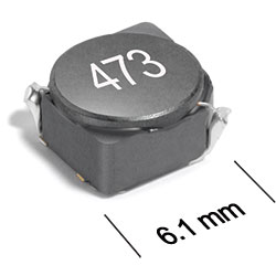
ST511PNA Series
Power Inductor for Critical Applications
ST511PNA Series offers low DCR and excellent current handling.
- 6.1 × 6.1 mm footprint; 3.2 mm high shielded inductors.
- Gold over nickel over phos bronze terminations. Other terminations available at additional cost.
Specifications
Electrical specifications at 25°C.
| Part number 1 |
Inductance (µH)
2
(Tolerance: ±20%) |
DCR max (Ω) | SRF typ (MHz) 3 | Isat (A) 4 | Irms (A) 5 | |||
|---|---|---|---|---|---|---|---|---|
| 10% drop | 20% drop | 30% drop | 20°C rise | 40°C rise | ||||
| ST511PNA472MLZ | 4.7 | 0.056 | 65 | 2.18 | 2.60 | 2.84 | 2.30 | 3.10 |
| ST511PNA562MLZ | 5.6 | 0.060 | 60 | 2.10 | 2.50 | 2.74 | 2.20 | 2.95 |
| ST511PNA682MLZ | 6.8 | 0.065 | 47 | 1.80 | 2.12 | 2.30 | 2.10 | 2.80 |
| ST511PNA822MLZ | 8.2 | 0.070 | 45 | 1.78 | 2.06 | 2.22 | 2.00 | 2.65 |
| ST511PNA103MLZ | 10 | 0.085 | 39 | 1.36 | 1.64 | 1.84 | 1.90 | 2.50 |
| ST511PNA123MLZ | 12 | 0.110 | 33 | 1.30 | 1.54 | 1.70 | 1.75 | 2.35 |
| ST511PNA153MLZ | 15 | 0.135 | 27 | 1.16 | 1.42 | 1.56 | 1.65 | 2.20 |
| ST511PNA183MLZ | 18 | 0.160 | 24 | 1.04 | 1.22 | 1.36 | 1.55 | 2.05 |
| ST511PNA223MLZ | 22 | 0.190 | 21 | 0.97 | 1.12 | 1.22 | 1.45 | 1.90 |
| ST511PNA273MLZ | 27 | 0.235 | 19 | 0.91 | 1.08 | 1.18 | 1.30 | 1.75 |
| ST511PNA333MLZ | 33 | 0.310 | 18 | 0.81 | 0.96 | 1.10 | 1.20 | 1.60 |
| ST511PNA393MLZ | 39 | 0.345 | 17 | 0.79 | 0.92 | 0.99 | 1.10 | 1.45 |
| ST511PNA473MLZ | 47 | 0.380 | 16 | 0.72 | 0.86 | 0.93 | 0.95 | 1.30 |
| ST511PNA563MLZ | 56 | 0.430 | 14 | 0.61 | 0.72 | 0.79 | 0.85 | 1.15 |
| ST511PNA683MLZ | 68 | 0.580 | 12 | 0.55 | 0.63 | 0.69 | 0.73 | 1.00 |
| ST511PNA823MLZ | 82 | 0.640 | 10 | 0.53 | 0.62 | 0.67 | 0.60 | 0.85 |
| ST511PNA104MLZ | 100 | 0.820 | 9 | 0.45 | 0.54 | 0.59 | 0.50 | 0.69 |
Notes
- When ordering, please specify termination and screening codes: ST511PNA104MLZ.
- Inductance tested at 100 kHz, 0.1 Vrms, 0 Adc using an Agilent/HP 4263B LCR meter or equivalent.
- SRF measured using Agilent/HP 4191A or equilvalent.
- DC current at 25°C that causes the specified inductance drop from its value without current.
- Current that causes the specified temperature rise from 25°C ambient. This information is for reference only and does not represent absolute maximum ratings.
Termination:
- L = Gold over nickel over phos bronze.
- T = Tin-silver-copper (95.5/4/0.5). (Special order, added cost)
- S = Tin-lead (63/37). (Special order, added cost)
Screening:
- Z = Unscreened
- Y = Unscreened (SLDC Option A)
- W = Unscreened (SLDC Option B)
- H = Group A screening per Coilcraft CP-SA-10001
- G= Coilcraft CP-SA-10001 Group A (SLDC Option A)
- D = Coilcraft CP-SA-10001 Group A (SLDC Option B)
Custom screening also available.
Environmental
Ambient temperature range:
–40°C to +85°C with (40°C rise) Irms current.
Storage temperature range:
Component: –55°C to +125°C.
Tape and reel packaging: –40°C to +80°C.
Tape and reel packaging: –40°C to +80°C.
Maximum part temperature:
+125°C (ambient + temp rise).
Failures in Time (FIT) / Mean Time Between Failures (MTBF):
Performance curves
L vs Frequency

L vs Current


General specification
Core Material:
Ferrite
Weight:
0.33 – 0.38 g
Packaging:
500/7′′ reel; Plastic tape: 16 mm wide, 0.3 mm thick, 12 mm pocket spacing, 3.1 mm pocket depth.
Soldering/Washing
Moisture Sensitivity Level (MSL):
1 (unlimited floor life at <30°C / 85% relative humidity).
Resistance to soldering heat:
Max three 40 second reflows at +260°C, parts cooled to room temperature between cycles.
Refer to Soldering Coilcraft Components before soldering.