Datasheet
3D Model
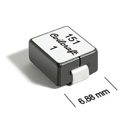
ST534PMM Series
Shielded Power Inductors
ST534PMM Series designed for use in multi-phase VRM/VRD regulators and high current/high frequency DC/DC converters.
- Requires only 70 mm2 of board space; can handle up to 61 A.
- Matte tin over nickel over copper. Other terminations available at additional cost.
Specifications
Electrical specifications at 25°C.
| Part number 1 |
Inductance (µH)
2
(Tolerance: ±20%) |
DCR ± 7% (mΩ) 3 | SRF ref (MHz) 4 | Isat (A) 5 | Irms (A) 6 |
|---|---|---|---|---|---|
| ST534PMM750MLZ | 0.075 | 0.230 | 200 | 61.0 | 43 |
| ST534PMM101MLZ | 0.100 | 0.230 | 145 | 50.0 | 43 |
| ST534PMM121MLZ | 0.125 | 0.230 | 140 | 37.0 | 43 |
| ST534PMM151MLZ | 0.150 | 0.230 | 133 | 30.0 | 43 |
| ST534PMM231MLZ | 0.230 | 0.230 | 70 | 25.5 | 43 |
Notes
- When ordering, please specify termination and testing codes: ST534PMM231MLZ.
- Inductance tested at 100 kHz, 0.1 Vrms using an Agilent/HP 4263B LCR meter or equivalent.
- DCR is measured on a micro-ohmmeter at points indicated in the dimensional diagram.
- This information is for design purposes only and shall not be tested during screening.
- DC current at 25°C that causes a 20% (typ) inductance drop from its value without current.
- Current that causes the specified temperature rise from 25°C ambient. This information is for reference only and does not represent absolute maximum ratings.
Due to the design of this component, DWV and IR shall not be specified or tested.
Termination:
- L = Matte tin over nickel over copper
- T = Tin-silver-copper (95.5/4/0.5). (Special order, added cost)
- S = Tin-lead (63/37). (Special order, added cost)
Screening:
- Z = Unscreened
- Y = Unscreened (SLDC Option A)
- W = Unscreened (SLDC Option B)
- H = Group A screening per Coilcraft CP-SA-10001
- G = Coilcraft CP-SA-10001 Group A (SLDC Option A)
- D = Coilcraft CP-SA-10001 Group A (SLDC Option B)
Environmental
Ambient temperature range:
–40°C to +85°C with Irms current.
Storage temperature range:
Component: –55°C to +125°C.
Tape and reel packaging: –40°C to +80°C.
Tape and reel packaging: –40°C to +80°C.
Maximum part temperature:
+125°C (ambient + temp rise).
Failures in Time (FIT) / Mean Time Between Failures (MTBF):
Performance curves
L vs Current

L vs Frequency

ESR vs Frequency

Typical Temperature Rise vs Current

.png "st534pmm_dim-(1).png")
General specification
Core Material:
Ferrite
Weight:
1.1 – 1.5 g
Packaging:
250/7″ reel Plastic tape: 24 mm wide, 0.35 mm thick, 12 mm pocket spacing, 5.08 mm pocket depth.
Soldering/Washing
Moisture Sensitivity Level (MSL):
1 (unlimited floor life at <30°C / 85% relative humidity).
Resistance to soldering heat:
Max three 40 second reflows at +260°C, parts cooled to room temperature between cycles.
Refer to Soldering Coilcraft Components before soldering.
PCB Washing:
Tested with pure water or alcohol only. For other solvents, see Doc787_PCB_Washing.pdf.