Datasheet
3D Model
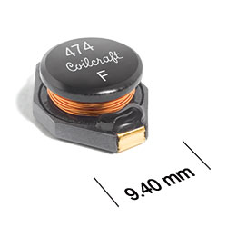
ST563PKP Series
Power Inductors for Critical Applications
ST563PKP Series offers high energy storage and very low resistance.
- High inductance values are perfect for EL driver applications.
- Gold over nickel over phos bronze. Other terminations available at additional cost.
Specifications
Electrical specifications at 25°C.
| Part number 1 | Inductance (µH) 2 | Tolerance (%) 3 | DCR max (Ω) | SRF typ (MHz) 4 | Isat (A) 5 | Irms (A) 6 |
|---|---|---|---|---|---|---|
| ST563PKP102MLZ | 1.0 | 20 | 0.0090 | 100 | 9.0 | 6.8 |
| ST563PKP152MLZ | 1.5 | 20 | 0.010 | 90.0 | 8.0 | 6.4 |
| ST563PKP222_LZ | 2.2 | 20,10 | 0.012 | 80.0 | 7.0 | 6.1 |
| ST563PKP332_LZ | 3.3 | 20,10 | 0.015 | 65.0 | 6.4 | 5.4 |
| ST563PKP472_LZ | 4.7 | 20,10 | 0.018 | 45.0 | 5.4 | 4.8 |
| ST563PKP682_LZ | 6.8 | 20,10 | 0.026 | 38.0 | 4.6 | 4.4 |
| ST563PKP103_LZ | 10 | 20,10 | 0.038 | 30.0 | 3.8 | 3.9 |
| ST563PKP153_LZ | 15 | 20,10 | 0.046 | 27.0 | 3.0 | 3.1 |
| ST563PKP223_LZ | 22 | 20,10 | 0.085 | 19.0 | 2.3 | 2.7 |
| ST563PKP333_LZ | 33 | 20,10 | 0.10 | 15.0 | 2.0 | 2.1 |
| ST563PKP473_LZ | 47 | 20,10 | 0.14 | 12.0 | 1.6 | 1.8 |
| ST563PKP683_LZ | 68 | 20,10 | 0.20 | 10.0 | 1.4 | 1.5 |
| ST563PKP104_LZ | 100 | 20,10 | 0.28 | 9.0 | 1.2 | 1.3 |
| ST563PKP154_LZ | 150 | 20,10 | 0.40 | 6.0 | 1.0 | 1.0 |
| ST563PKP224_LZ | 220 | 20,10 | 0.61 | 5.0 | 0.80 | 0.80 |
| ST563PKP334_LZ | 330 | 20,10 | 1.0 | 4.5 | 0.60 | 0.60 |
| ST563PKP474_LZ | 470 | 20,10 | 1.3 | 3.5 | 0.50 | 0.50 |
| ST563PKP684_LZ | 680 | 20,10 | 2.0 | 2.5 | 0.40 | 0.40 |
| ST563PKP105_LZ | 1000 | 20,10 | 3.0 | 2.0 | 0.30 | 0.30 |
| ST563PKP155_LZ | 1500 | 20,10 | 4.5 | 1.7 | 0.29 | 0.27 |
| ST563PKP335_LZ | 3300 | 20,10 | 9.0 | 1.1 | 0.19 | 0.17 |
Notes
- When ordering, specify tolerance, termination and screening codes: e.g. ST563PKP105MLZ.
- Tested at 100 kHz, 0.1 Vrms, 0 Adc using an Agilent/HP 4263B LCR meter or equivalent.
- Tolerances in bold are stocked for immediate shipment.
- SRF >13 MHz measured using Agilent/HP 8753D network analyzer; <13 MHz using Agilent/HP 4192A.
- DC current at 25°C that causes a 10% (typ) inductance drop from its value without current.
- Current that causes a 40°C temperature rise from 25°C ambient. This information is for reference only and does not represent absolute maximum ratings.
Tolerance:
- M = 20%
- K = 10%
Termination:
- L = Gold over nickel over phos bronze.
- T = Tin-silver-copper (95.5/4/0.5). (Special order, added cost)
- S = Tin-lead (63/37). (Special order, added cost)
Testing:
- Z = Unscreened
- Y = Unscreened (SLDC Option A)
- W = Unscreened (SLDC Option B)
- H = Group A screening per Coilcraft CP-SA-10001
- G = Coilcraft CP-SA-10001 Group A (SLDC Option A)
- D = Coilcraft CP-SA-10001 Group A (SLDC Option B)
Environmental
Ambient temperature range:
–40°C to +85°C with Irms current, +85°C to +125°C with derated current.
Storage temperature range:
Component: –55°C to +125°C.
Tape and reel packaging: –55°C to +80°C.
Tape and reel packaging: –55°C to +80°C.
Failures in Time (FIT) / Mean Time Between Failures (MTBF):
Performance curves
Typical L vs Current

Typical L vs Frequency


General specification
Core Material:
Ferrite
Weight:
0.92– 1.23 g
Packaging:
1000 per 13″ reel Plastic tape: 24 mm wide, 0.33 mm thick, 12 mm pocket spacing, 5.8 mm pocket depth.
Soldering/Washing
Moisture Sensitivity Level (MSL):
1 (unlimited floor life at <30°C / 85% relative humidity).
Resistance to soldering heat:
Max three 40 second reflows at +260°C, parts cooled to room temperature between cycles.
Refer to Soldering Coilcraft Components before soldering.