Datasheet
3D Model
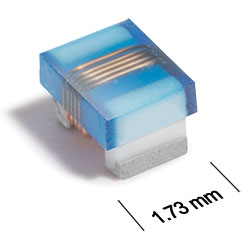
AE336RAD Series
Outgassing Compliant Chip Inductors
The AE336RAD Series is not recommended for new designs, but existing customers will continue to be supported. As an alternative, we recommend the AR336RAD Series which is a drop-in replacement.
The AE336RAD inductors provide exceptional Q values, even at high frequencies. They have a ceramic body and wire wound construction to provide the highest SRFs, tight inductance tolerance and batch consistency.
This robust version of Coilcraft’s standard 0805HQ series features high temperature materials that pass NASA low outgassing specifications and allow operation in ambient temperatures up to 155°C. The standard tin-lead (Sn-Pb) terminations ensure the best possible board adhesion.
All parts are qualified and compliant with MIL-STD-981 Family 50, Class S.
All parts are qualified and compliant with MIL-STD-981 Family 50, Class S.
Specifications
Electrical specifications at 25°C.
| Part number 1 | Inductance (nH) 2 | Tolerance (%) | Q min 3 | SRF min (GHz) 4 | DCR max (Ω) 5 | Imax (mA) |
|---|---|---|---|---|---|---|
| AE336RAD2N5JPZ | 2.5 @ 250 MHz | 5 | 56 @ 1000 MHz | > 5.00 | 0.020 | 2000 |
| AE336RAD5N6JPZ | 5.6 @ 250 MHz | 5 | 83 @ 1000 MHz | 4.88 | 0.035 | 1900 |
| AE336RAD6N2JPZ | 6.2 @ 250 MHz | 5 | 80 @ 1000 MHz | 4.55 | 0.035 | 1800 |
| AE336RAD12NJPZ | 12 @ 250 MHz | 5 | 52 @ 500 MHz | 2.80 | 0.045 | 1600 |
| AE336RAD16N_PZ | 16 @ 250 MHz | 5,2 | 72 @ 500 MHz | 2.40 | 0.060 | 1400 |
| AE336RAD18N_PZ | 18 @ 250 MHz | 5,2 | 70 @ 500 MHz | 2.20 | 0.060 | 1400 |
| AE336RAD20N_PZ | 20 @ 250 MHz | 5,2 | 54 @ 250 MHz | 2.05 | 0.060 | 1400 |
| AE336RAD27N_PZ | 27 @ 250 MHz | 5,2,1 | 58 @ 250 MHz | 2.00 | 0.070 | 1300 |
| AE336RAD30N_PZ | 30 @ 250 MHz | 5,2,1 | 50 @ 250 MHz | 1.74 | 0.095 | 1100 |
| AE336RAD39N_PZ | 39 @ 250 MHz | 5,2,1 | 53 @ 250 MHz | 1.60 | 0.110 | 1000 |
| AE336RAD48N_PZ | 48 @ 200 MHz | 5,2,1 | 44 @ 150 MHz | 1.40 | 0.095 | 1100 |
| AE336RAD51N_PZ | 51 @ 200 MHz | 5,2,1 | 36 @ 150 MHz | 1.28 | 0.120 | 900 |
Notes
- When ordering, please specify tolerance, termination and screening codes: e.g. AE336RAD51NGPZ.
- Inductance measured using a Coilcraft SMD-A fixture in an Agilent/HP 4286 impedance analyzer or equivalent with Coilcraft-provided correlation pieces.
- Q measured at the same frequency as inductance using an Agilent/HP 4291A with an Agilent/HP 16197 test fixture or equivalents.
- SRF measured using an Agilent/HP 8753ES network analyzer or equivalent and a Coilcraft SMD-D test fixture.
- DCR measured on a Keithley 580 micro-ohmmeter or equivalent and a Coilcraft CCF858 test fixture.
Tolerance:
- F = 1%
- G = 2%
- J = 5%
Termination:
- P = Tin-lead (63/37) over tin over nickel over silver-platinum-glass frit.
- C = Tin-lead (63/37) over gold over nickel over moly-mag.
- S = Tin-lead (63/37) over leach-resistant silver-platinum-glass frit.
- A = Gold over nickel over moly-mag.
- L = Silver-palladium-platinum-glass frit.
Screening:
- Z = Unscreened
- H = Coilcraft CP-SA-10001 Group A
- 1 = EEE-INST-002 (Family 3) Level 1
- 2 = EEE-INST-002 (Family 3) Level 2
- 3 = EEE-INST-002 (Family 3) Level 3
- 4 = MIL-STD-981 (Family 50) Class B
- 5 = MIL-STD-981 (Family 50) Class S
- Screening performed to the document’s latest revision.
- Lot qualification (Group B) available.
- Testing T and U have been replaced with more detailed codes 4, 5, and 1, 2, 3, respectively. Codes T and U can still be used, if necessary. Custom testing also available.
- Country of origin restrictions available; prefix options G or F.
Environmental
Ambient temperature range:
–55°C to +125°C with Imax current.
Storage temperature range:
Component: –55°C to +155°C.
Packaging: –55°C to +80°C.
Packaging: –55°C to +80°C.
Maximum part temperature:
+155°C (ambient + temp rise).
Failures in Time (FIT) / Mean Time Between Failures (MTBF):
Performance curves
Typical Q vs Frequency

Typical L vs Frequency


General specification
Core Material:
Ceramic
Packaging:
2000 per 7′′ reel Plastic tape: 8 mm wide, 0.23 mm thick, 4 mm pocket spacing, 1.65 mm pocket depth
Temperature coefficient of inductance:
+25 to +155 ppm/°C.
Soldering/Washing
Moisture Sensitivity Level (MSL):
1 (unlimited floor life at <30°C / 85% relative humidity).
Resistance to soldering heat:
Max three 40 second reflows at +260°C, parts cooled to room temperature between cycles.
Refer to Soldering Coilcraft Components before soldering.