Datasheet
3D Model
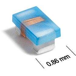
AR312RAG Series
Outgassing Compliant Chip Inductors
Coilcraft AR312RAG Series offers higher Q and lower DCR than other 0603 inductors.
- Highest SRF values – as high as 16 GHz.
- High temperature materials allow operation in ambient temperatures up to 155°C.
- Passes NASA low outgassing specifications.
- Standard tin-lead (Sn-Pb) terminations ensures the best possible board adhesion. Note: Nickel barrier termination (tin-lead over tin over nickel over silver-platinum-glass frit, termination code P) is recommended for hand soldering applications.
- Tin-lead (63/37) over tin over nickel over silver-platinum-glass frit terminations. Other terminations are also available.
Specifications
Electrical specifications at 25°C.
Highlighted parts are not compliant with MIL-STD-981 Family 50, Class S due to wire gauge
| Part number 1 | Inductance (nH) 2 | Tolerance (%) | 900 MHz | 1.7 GHz |
Q min
@ 250 MHz 3 |
SRF min (GHz) 4 | DCR max (Ω) 5 | Imax (mA) | ||
|---|---|---|---|---|---|---|---|---|---|---|
| L typ | Q typ 3 | L typ | Q typ 3 | |||||||
| AR312RAG1N8JPZ | 1.8 @ 250 MHz | 5 | 1.77 | 40 | 1.77 | 65 | 17 | > 5.0 | 0.035 | 800 |
| AR312RAG3N3_PZ | 3.3 @ 250 MHz | 5,2 | 3.28 | 67 | 3.32 | 104 | 35 | > 5.0 | 0.030 | 800 |
| AR312RAG3N6_PZ | 3.6 @ 250 MHz | 5,2 | 3.59 | 70 | 3.62 | 116 | 32 | > 5.0 | 0.033 | 800 |
| AR312RAG3N9_PZ | 3.9 @ 250 MHz | 5,2 | 3.88 | 68 | 3.95 | 108 | 33 | > 5.0 | 0.045 | 800 |
| AR312RAG4N3_PZ | 4.3 @ 250 MHz | 5,2 | 4.29 | 58 | 4.31 | 91 | 28 | > 5.0 | 0.080 | 710 |
| AR312RAG4N7_PZ | 4.7 @ 250 MHz | 5,2 | 4.65 | 48 | 4.71 | 75 | 22 | > 5.0 | 0.100 | 720 |
| AR312RAG5N1_PZ | 5.1 @ 250 MHz | 5,2 | 5.08 | 84 | 5.12 | 140 | 38 | > 5.0 | 0.042 | 800 |
| AR312RAG5N6_PZ | 5.6 @ 250 MHz | 5,2 | 5.6 | 87 | 5.73 | 145 | 43 | > 5.0 | 0.042 | 800 |
| AR312RAG6N0_PZ | 6.0 @ 250 MHz | 5,2 | 5.92 | 94 | 6.12 | 154 | 40 | 4.8 | 0.053 | 800 |
| AR312RAG6N8_PZ | 6.8 @ 250 MHz | 5,2 | 6.83 | 88 | 7.05 | 143 | 34 | 4.6 | 0.050 | 800 |
| AR312RAG7N2_PZ | 7.2 @ 250 MHz | 5,2 | 7.25 | 96 | 7.38 | 139 | 36 | 4.3 | 0.080 | 800 |
| AR312RAG7N5_PZ | 7.5 @ 250 MHz | 5,2 | 7.55 | 81 | 7.85 | 112 | 32 | 4.2 | 0.100 | 800 |
| AR312RAG8N2_PZ | 8.2 @ 250 MHz | 5,2 | 8.21 | 96 | 8.39 | 148 | 37 | 4.7 | 0.054 | 800 |
| AR312RAG8N7_PZ | 8.7 @ 250 MHz | 5,2 | 8.73 | 97 | 9.0 | 149 | 33 | 4.4 | 0.054 | 800 |
| AR312RAG9N1_PZ | 9.1 @ 250 MHz | 5,2 | 9.18 | 76 | 9.64 | 109 | 38 | 4.1 | 0.054 | 800 |
| AR312RAG9N5_PZ | 9.5 @ 250 MHz | 5,2 | 9.56 | 98 | 9.99 | 149 | 40 | 3.9 | 0.053 | 800 |
| AR312RAG10N_PZ | 10 @ 250 MHz | 5,2 | 10.16 | 90 | 10.64 | 142 | 38 | 3.4 | 0.054 | 800 |
| AR312RAG11N_PZ | 11 @ 250 MHz | 5,2 | 11.06 | 78 | 11.82 | 108 | 36 | 3.3 | 0.075 | 800 |
| AR312RAG12N_PZ | 12 @ 250 MHz | 5,2 | 12.26 | 69 | 13.2 | 91 | 32 | 3.3 | 0.110 | 750 |
| AR312RAG15N_PZ | 15 @ 250 MHz | 5,2 | 15.41 | 83 | 17.2 | 124 | 36 | 2.9 | 0.085 | 800 |
| AR312RAG16N_PZ | 16 @ 250 MHz | 5,2 | 16.37 | 77 | 18.7 | 116 | 32 | 2.8 | 0.095 | 790 |
| AR312RAG18N_PZ | 18 @ 250 MHz | 5,2 | 18.56 | 76 | 20.9 | 100 | 34 | 2.6 | 0.075 | 800 |
| AR312RAG22N_PZ | 22 @ 250 MHz | 5,2 | 22.7 | 77 | 25.9 | 88 | 30 | 2.5 | 0.140 | 600 |
| AR312RAG23N_PZ | 23 @ 250 MHz | 5,2 | 24 | 69 | 29.53 | 80 | 36 | 2.4 | 0.195 | 560 |
| AR312RAG24N_PZ | 24 @ 250 MHz | 5,2 | 24.9 | 77 | 28.9 | 91 | 43 | 2.4 | 0.085 | 800 |
| AR312RAG27N_PZ | 27 @ 250 MHz | 5,2 | 28.4 | 74 | 34 | 84 | 34 | 2.2 | 0.150 | 620 |
| AR312RAG30N_PZ | 30 @ 250 MHz | 5,2 | 31.5 | 82 | 37.9 | 82 | 40 | 2.2 | 0.130 | 720 |
| AR312RAG33N_PZ | 33 @ 250 MHz | 5,2 | 34.9 | 76 | 42.9 | 80 | 38 | 2.2 | 0.170 | 560 |
| AR312RAG36N_PZ | 36 @ 250 MHz | 5,2 | 38.5 | 69 | 50 | 64 | 36 | 2.0 | 0.225 | 480 |
| AR312RAG39N_PZ | 39 @ 250 MHz | 5,2 | 41.5 | 78 | 51.9 | 74 | 38 | 2.0 | 0.190 | 540 |
| AR312RAG43N_PZ | 43 @ 250 MHz | 5,2 | 45.7 | 83 | 58.1 | 76 | 36 | 2.0 | 0.170 | 630 |
| AR312RAG47N_PZ | 47 @ 200 MHz | 5,2 | 50.6 | 77 | 66.9 | 72 | 39 | 1.8 | 0.270 | 440 |
| AR312RAG51N_PZ | 51 @ 200 MHz | 5,2 | 54.6 | 73 | 71.3 | 62 | 37 | 1.8 | 0.280 | 440 |
| AR312RAG56N_PZ | 56 @ 200 MHz | 5,2 | 60.3 | 74 | 79.9 | 56 | 36 | 1.8 | 0.300 | 420 |
| AR312RAG68N_PZ | 68 @ 200 MHz | 5,2 | 75.5 | 73 | 113.3 | 49 | 37 | 1.6 | 0.330 | 400 |
| AR312RAG72N_PZ | 72 @ 150 MHz | 5,2 | 80.8 | 69 | - | - | 36 | 1.5 | 0.420 | 380 |
| AR312RAG75N_PZ | 75 @ 150 MHz | 5,2 | 84.6 | 71 | - | - | 36 | 1.5 | 0.520 | 340 |
| AR312RAG82N_PZ | 82 @ 150 MHz | 5,2 | 94 | 62 | - | - | 36 | 1.4 | 0.460 | 350 |
| AR312RAG91N_PZ | 91 @ 150 MHz | 5,2 | 103 | 64 | - | - | 36 | 1.3 | 0.580 | 310 |
| AR312RAGR10_PZ | 100 @ 150 MHz | 5,2 | 114 | 69 | - | - | 36 | 1.4 | 0.540 | 340 |
| AR312RAGR11_PZ | 110 @ 150 MHz | 5,2 | 126.2 | 63 | - | - | 35 | 1.3 | 0.580 | 310 |
| AR312RAGR12_PZ | 120 @ 150 MHz | 5,2 | 142.4 | 61 | - | - | 36 | 1.2 | 0.720 | 280 |
| AR312RAGR15_PZ | 150 @ 150 MHz | 5,2 | 188.8 | 57 | - | - | 36 | 1.1 | 0.820 | 260 |
| AR312RAGR18_PZ | 180 @ 100 MHz | 5,2 | 232.2 | 50 | - | - | 36 | 1.0 | 1.500 | 190 |
| AR312RAGR20_PZ | 200 @ 100 MHz | 5,2 | 265 | 47 | - | - | 36 | 1.0 | 2.000 | 180 |
| AR312RAGR21_PZ | 210 @ 100 MHz | 5,2 | 288 | 45 | - | - | 36 | 0.96 | 2.000 | 170 |
| AR312RAGR22_PZ | 220 @ 100 MHz | 5,2 | 315 | 41 | - | - | 36 | 0.88 | 2.000 | 170 |
| AR312RAGR27_PZ | 270 @ 100 MHz | 5,2 | - | - | - | - | 35 | 0.84 | 2.400 | 170 |
| AR312RAGR30_PZ | 300 @ 100 MHz | 5,2 | - | - | - | - | 35 | 0.79 | 2.400 | 220 |
Notes
- When ordering, please specify tolerance, termination and screening codes: e.g. AR312RAG39NGPZ.
- Inductance measured at specified test frequency using a Coilcraft SMD-A test fixture and Coilcraft-provided correlation pieces with an Agilent/HP 4286A impedance analyzer or equivalent.
- Q measured using an Agilent/HP 4291A with an Agilent/HP 16197A test fixture or equivalents.
- SRF measured using an Agilent/HP 8753ES network analyzer or equivalent and a Coilcraft CCF1232 test fixture.
- DCR measured on a Keithley 580 micro-ohmmeter or equivalent and a Coilcraft CCF1010 test fixture.
Tolerance:
- G= 2%
- J = 5%
Termination:
For hand soldering applications, the nickel barrier termination (tin-lead over tin over nickel over silver-platinum-glass frit, termination code P) is recommended. Exposed gold or tin in the terminations migrates into the solder.- P = Tin-lead (63/37) over tin over nickel over silverplatinum-glass frit.
- C = Tin-lead (63/37) over gold over nickel over moly-mag.
- S = Tin-lead (63/37) over leach-resistant silver-platinumglass frit.
- A = Gold over nickel over moly-mag.
- L = Silver-palladium-platinum-glass frit.
Screening:
- Z = Unscreened
- H = Coilcraft CP-SA-10001 Group A
- 1 = EEE-INST-002 (Family 3) Level 1
- 2 = EEE-INST-002 (Family 3) Level 2
- 3 = EEE-INST-002 (Family 3) Level 3
- 4 = MIL-STD-981 (Family 50) Class B
- 5 = MIL-STD-981 (Family 50) Class S
- F = ESCC3201 (F4 operational life performed at 90°C)
- Screening performed to the document’s latest revision.
- Lot qualification (Group B) available.
- Testing T and U have been replaced with more detailed codes 4, 5, and 1, 2, 3, respectively. Codes T and U can still be used, if necessary. Custom testing also available.
- Country of origin restrictions available; prefix options G or F.
Environmental
Ambient temperature range:
–55°C to +125°C with Imax current.
Storage temperature range:
Component: –55°C to +155°C.
Tape and reel packaging: –55°C to +80°C.
Tape and reel packaging: –55°C to +80°C.
Maximum part temperature:
+155°C (ambient + temp rise).
Failures in Time (FIT) / Mean Time Between Failures (MTBF):
Performance curves
Typical L vs Frequency

Typical Q vs Frequency


General specification
Core Material:
Ceramic
Weight:
2.0 – 4.0 mg
Packaging:
2000 per 7″ reel. Paper tape: 8 mm wide, 1 mm thick, 4 mm pocket spacing.
Temperature coefficient of inductance:
+25 to +155 ppm/°C.
Soldering/Washing
Moisture Sensitivity Level (MSL):
1 (unlimited floor life at <30°C / 85% relative humidity).
Resistance to soldering heat:
Max three 40 second reflows at +260°C, parts cooled to room temperature between cycles.
Refer to Soldering Coilcraft Components before soldering.