Datasheet
3D Model
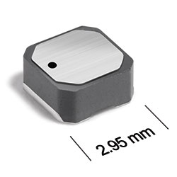
ML412PJB Series
High-Reliability Power Inductors
ML412PJB Series offers high temperature materials allowing operation in ambient temperatures up to 155°C.
- Special construction allows it to pass vibration testing to 80 G and shock testing to 1000 G.
- Silver-palladium-platinum-glass frit terminations. Other terminations available at an additional cost.
Specifications
Electrical specifications at 25°C.
| Part number 1 |
Inductance (µH)
2
(Tolerance: ±20%) |
DCR max (Ω) 3 | SRF (MHz) 4 | Isat (A) 5 | Irms (A) 6 | ||||
|---|---|---|---|---|---|---|---|---|---|
| min | typ | 10% drop | 20% drop | 30% drop | 20°C rise | 40°C rise | |||
| ML412PJB102MLZ | 1.0 | 0.075 | 133 | 190 | 1.8 | 2.0 | 2.1 | 1.1 | 1.6 |
| ML412PJB152MLZ | 1.5 | 0.10 | 98.0 | 140 | 1.8 | 2.1 | 2.2 | 1.0 | 1.4 |
| ML412PJB182MLZ | 1.8 | 0.10 | 94.5 | 135 | 1.5 | 1.7 | 2.1 | 0.88 | 1.1 |
| ML412PJB222MLZ | 2.2 | 0.11 | 77.0 | 110 | 2.0 | 2.0 | 2.1 | 0.88 | 1.1 |
| ML412PJB332MLZ | 3.3 | 0.13 | 63.0 | 90.0 | 1.4 | 1.5 | 1.5 | 0.80 | 1.1 |
| ML412PJB472MLZ | 4.7 | 0.20 | 55.3 | 79.0 | 1.1 | 1.2 | 1.2 | 0.72 | 1.0 |
| ML412PJB682MLZ | 6.8 | 0.30 | 40.6 | 58.0 | 0.83 | 0.86 | 0.89 | 0.54 | 0.72 |
| ML412PJB103MLZ | 10 | 0.44 | 33.6 | 48.0 | 0.60 | 0.69 | 0.73 | 0.44 | 0.60 |
| ML412PJB153MLZ | 15 | 0.70 | 24.5 | 35.0 | 0.58 | 0.61 | 0.62 | 0.35 | 0.47 |
| ML412PJB183MLZ | 18 | 0.75 | 23.1 | 33.0 | 0.56 | 0.58 | 0.59 | 0.34 | 0.46 |
| ML412PJB223MLZ | 22 | 0.83 | 21.0 | 30.0 | 0.48 | 0.49 | 0.50 | 0.34 | 0.46 |
| ML412PJB333MLZ | 33 | 1.3 | 16.1 | 23.0 | 0.39 | 0.41 | 0.42 | 0.28 | 0.38 |
| ML412PJB473MLZ | 47 | 1.6 | 11.9 | 17.0 | 0.36 | 0.38 | 0.39 | 0.24 | 0.32 |
| ML412PJB683MLZ | 68 | 2.3 | 9.8 | 14.0 | 0.30 | 0.31 | 0.32 | 0.20 | 0.26 |
| ML412PJB104MLZ | 100 | 3.4 | 7.7 | 11.0 | 0.24 | 0.25 | 0.26 | 0.15 | 0.21 |
| ML412PJB124MLZ | 120 | 4.6 | 6.3 | 9.0 | 0.21 | 0.22 | 0.23 | 0.14 | 0.18 |
| ML412PJB154MLZ | 150 | 6.1 | 5.6 | 8.0 | 0.19 | 0.20 | 0.20 | 0.12 | 0.16 |
| ML412PJB184MLZ | 180 | 8.6 | 5.3 | 7.5 | 0.16 | 0.17 | 0.17 | 0.10 | 0.14 |
| ML412PJB224MLZ | 220 | 9.5 | 4.2 | 6.0 | 0.15 | 0.16 | 0.16 | 0.090 | 0.12 |
| ML412PJB334MLZ | 330 | 23.0 | 3.5 | 5.0 | 0.10 | 0.11 | 0.11 | 0.060 | 0.080 |
Notes
- When ordering, please specify termination and screening codes: e.g. ML412PJB334MLZ.
- Inductance tested at 100 kHz, 0.1 Vrms using an Agilent/HP 4192A. Inductance at 1 MHz is the same for parts with SRF ≥10 MHz.
- DCR measured on a micro-ohmmeter.
- SRF measured using an Agilent/HP 8753ES or equivalent.
- DC current that causes the specified inductance drop from its value without current.
- Current that causes the specified temperature rise from 25°C ambient. This information is for reference only and does not represent absolute maximum ratings.
Termination:
- L = Silver-palladium-platinum-glass frit
- R = Matte tin over nickel over silver
Screening:
- Z = Unscreened
- Y = Unscreened (SLDC Option A)
- W = Unscreened (SLDC Option B)
- H = Group A screening per Coilcraft CP-SA-10001
- G = Coilcraft CP-SA-10001 Group A (SLDC Option A)
- D = Coilcraft CP-SA-10001 Group A (SLDC Option B)
- Screening performed to the document’s latest revision.
- Custom testing also available.
- Country of origin restrictions available; prefix options G or F.
Environmental
Ambient temperature range:
–55°C to +105°C with (40°C) Irms current.
Storage temperature range:
Component: –55°C to +155°C.
Tape and reel packaging: –55°C to +80°C.
Tape and reel packaging: –55°C to +80°C.
Maximum part temperature:
+155°C (Ambient + temperature rise).
Failures in Time (FIT) / Mean Time Between Failures (MTBF):
Performance curves
Typical L vs Current

Typical L vs Frequency


General specification
Core Material:
Ferrite
Weight:
50 – 62 mg
Packaging:
1000/7″ reel Plastic tape: 12 mm wide, 0.26 mm thick, 8 mm pocket spacing, 1.65 mm pocket depth.
Soldering/Washing
Moisture Sensitivity Level (MSL):
1 (unlimited floor life at <30°C / 85% relative humidity).
Resistance to soldering heat:
Max three 40 second reflows at +260°C, parts cooled to room temperature between cycles.
Refer to Soldering Coilcraft Components before soldering.
Recommended Pick & Place Nozzle:
OD: 3 mm; ID: ≤1.5 mm.