Datasheet
3D Model
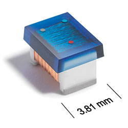
MS450RAA Series
High-Reliability Chip Inductors
MS450RAA Series offers 19 inductance values from 1.0 to 33 µH.
- Higher SRF values than 1812 size parts with ferrite cores.
- Tin-lead (63/37) over silver-platinum-glass frit. Other terminations available at an additional cost.
Specifications
Electrical specifications at 25°C.
| Part number 1 | Inductance (µH) 2 | Tolerance (%) | Q min 3 | SRF min (MHz) 4 | DCR max (Ω) 5 | Imax (mA) |
|---|---|---|---|---|---|---|
| MS450RAA102JSZ | 1.0 @ 7.9 MHz | 5,2 | 59 @ 50.0 MHz | 260 | 1.1 | 390 |
| MS450RAA122JSZ | 1.2 @ 7.9 MHz | 5,2 | 54 @ 50.0 MHz | 230 | 1.2 | 360 |
| MS450RAA152_SZ | 1.5 @ 7.9 MHz | 5,2 | 57 @ 50.0 MHz | 210 | 1.6 | 320 |
| MS450RAA182JSZ | 1.8 @ 7.9 MHz | 5,2 | 57 @ 50.0 MHz | 190 | 2.0 | 270 |
| MS450RAA222JSZ | 2.2 @ 7.9 MHz | 5,2 | 52 @ 50.0 MHz | 170 | 2.2 | 250 |
| MS450RAA272JSZ | 2.7 @ 7.9 MHz | 5,2 | 53 @ 50.0 MHz | 160 | 3.2 | 200 |
| MS450RAA332JSZ | 3.3 @ 7.9 MHz | 5,2 | 53 @ 50.0 MHz | 145 | 3.8 | 200 |
| MS450RAA392_SZ | 3.9 @ 7.9 MHz | 5,2 | 53 @ 50.0 MHz | 130 | 5.0 | 175 |
| MS450RAA472JSZ | 4.7 @ 7.9 MHz | 5,2 | 32 @ 10.0 MHz | 115 | 5.4 | 165 |
| MS450RAA562JSZ | 5.6 @ 7.9 MHz | 5 | 32 @ 10.0 MHz | 100 | 5.7 | 160 |
| MS450RAA682JSZ | 6.8 @ 7.9 MHz | 5 | 32 @ 10.0 MHz | 90 | 6.6 | 155 |
| MS450RAA822JSZ | 8.2 @ 7.9 MHz | 5,2 | 32 @ 10.0 MHz | 80 | 7.0 | 145 |
| MS450RAA103JSZ | 10.0 @ 7.9 MHz | 5 | 32 @ 10.0 MHz | 70 | 7.7 | 125 |
| MS450RAA123JSZ | 12.0 @ 2.5 MHz | 5 | 26 @ 5.0 MHz | 60 | 8.7 | 125 |
| MS450RAA153JSZ | 15.0 @ 2.5 MHz | 5 | 26 @ 5.0 MHz | 50 | 9.6 | 120 |
| MS450RAA183JSZ | 18.0 @ 2.5 MHz | 5 | 28 @ 5.0 MHz | 40 | 10.5 | 115 |
| MS450RAA223_SZ | 22.0 @ 2.5 MHz | 5,2 | 28 @ 5.0 MHz | 40 | 11.5 | 110 |
| MS450RAA273JSZ | 27.0 @ 2.5 MHz | 5 | 28 @ 5.0 MHz | 30 | 12.5 | 105 |
| MS450RAA333_SZ | 33.0 @ 2.5 MHz | 5,2 | 24 @ 2.5 MHz | 20 | 13.5 | 105 |
Notes
- When ordering, please specify tolerance and termination codes: e.g. MS450RAA333JSZ.
- Inductance measured using a Coilcraft SMD-A fixture in an Agilent/ HP 4286 impedance analyzer or equivalent with Coilcraft-provided correlation pieces.
- Q measured at the same frequency as inductance using an Agilent/ HP 4291A with an Agilent/HP 16193 test fixture or equivalents.
- SRF measured using an Agilent/HP 8753ES network analyzer or equivalent and a Coilcraft SMD-D test fixture.
- DCR measured on a micro-ohmmeter.
Tolerance:
- G= 2%
- J = 5%
Termination:
- S = Tin-lead (63/37) over silver-platinum-glass frit.
- T = Tin-silver-copper (95.5/4/0.5) over silver-platinumglass frit. (Special order, added cost)
- P = Tin-lead (63/37) over tin over nickel over silver-platinum-glass frit. (Special order, added cost)
- Q = Tin-silver-copper (95.5/4/0.5) over tin over nickel over silver-platinum-glass frit. (Special order, added cost)
Environmental
Ambient temperature range:
–55°C to +125°C with Imax current
Storage temperature range:
Component: –55°C to +155°C
Tape and reel packaging: –55°C to +80°C
Tape and reel packaging: –55°C to +80°C
Maximum part temperature:
+155°C (ambient + temp rise)
Failures in Time (FIT) / Mean Time Between Failures (MTBF):
Performance curves
L vs Frequency

Q vs Frequency


General specification
Core Material:
Ceramic
Weight:
102 – 142 mg
Packaging:
600 per 7″ reel Plastic tape: 12 mm wide, 0.3 mm thick, 8 mm pocket spacing, 3.7 mm pocket depth.
Temperature coefficient of inductance:
+25 to +155 ppm/°C
Soldering/Washing
Moisture Sensitivity Level (MSL):
1 (unlimited floor life at <30°C / 85% relative humidity)
Resistance to soldering heat:
Max three 40 second reflows at +260°C, parts cooled to room temperature between cycles.
Refer to Soldering Coilcraft Components before soldering.