Datasheet
3D Model
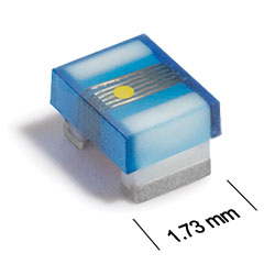
ST336RAA Series
Chip Inductors for Critical Applications
The ST336RAA inductors provide exceptional Q values, even at high frequencies.
They have a ceramic body and wire wound construction to provide the highest SRFs available in 0805 size.
Specifications
Electrical specifications at 25°C.
| Part number 1 | Inductance (nH) 2 | Tolerance (%) | Q min 3 | SRF min (MHz) 4 | DCR max (Ω) 5 | Imax (mA) | Color code |
|---|---|---|---|---|---|---|---|
| ST336RAA020JLZ | 2.8 @ 250 MHz | 5 | 57 @ 1000 MHz | 5000 | 0.06 | 800 | Gray |
| ST336RAA3N0JLZ | 3.0 @ 250 MHz | 5 | 61 @ 1000 MHz | 5000 | 0.06 | 800 | White |
| ST336RAA030JLZ | 3.3 @ 250 MHz | 5 | 48 @ 1000 MHz | 5000 | 0.08 | 600 | Black |
| ST336RAA050JLZ | 5.6 @ 250 MHz | 5 | 75 @ 1000 MHz | 4760 | 0.08 | 600 | Orange |
| ST336RAA060JLZ | 6.8 @ 250 MHz | 5 | 54 @ 1000 MHz | 4440 | 0.11 | 600 | Brown |
| ST336RAA070JLZ | 7.5 @ 250 MHz | 5 | 56 @ 1000 MHz | 3840 | 0.14 | 600 | Green |
| ST336RAA080_LZ | 8.2 @ 250 MHz | 5,2 | 63 @ 1000 MHz | 3560 | 0.12 | 600 | Red |
| ST336RAA100_LZ | 10 @ 250 MHz | 5,2 | 57 @ 500 MHz | 3460 | 0.10 | 600 | Blue |
| ST336RAA120_LZ | 12 @ 250 MHz | 5,2 | 46 @ 500 MHz | 3180 | 0.15 | 600 | Orange |
| ST336RAA150_LZ | 15 @ 250 MHz | 5,2 | 41 @ 500 MHz | 2560 | 0.17 | 600 | Yellow |
| ST336RAA180_LZ | 18 @ 250 MHz | 5,2 | 48 @ 500 MHz | 2480 | 0.20 | 600 | Green |
| ST336RAA220_LZ | 22 @ 250 MHz | 5,2 | 59 @ 500 MHz | 2080 | 0.22 | 500 | Blue |
| ST336RAA240_LZ | 24 @ 250 MHz | 5,2 | 59 @ 500 MHz | 1920 | 0.22 | 500 | Gray |
| ST336RAA270_LZ | 27 @ 250 MHz | 5,2 | 56 @ 500 MHz | 2060 | 0.25 | 500 | Violet |
| ST336RAA330_LZ | 33 @ 250 MHz | 5,2,1 | 64 @ 500 MHz | 1720 | 0.27 | 500 | Gray |
| ST336RAA360_LZ | 36 @ 250 MHz | 5,2,1 | 57 @ 500 MHz | 1520 | 0.27 | 500 | Orange |
| ST336RAA390_LZ | 39 @ 250 MHz | 5,2,1 | 44 @ 250 MHz | 1600 | 0.29 | 500 | White |
| ST336RAA430_LZ | 43 @ 200 MHz | 5,2,1 | 45 @ 250 MHz | 1440 | 0.34 | 500 | Yellow |
| ST336RAA470_LZ | 47 @ 200 MHz | 5,2,1 | 44 @ 250 MHz | 1360 | 0.31 | 470 | Black |
| ST336RAA560_LZ | 56 @ 200 MHz | 5,2,1 | 49 @ 250 MHz | 1280 | 0.34 | 460 | Brown |
| ST336RAA680_LZ | 68 @ 200 MHz | 5,2,1 | 52 @ 250 MHz | 1200 | 0.38 | 440 | Red |
| ST336RAA820_LZ | 82 @ 150 MHz | 5,2,1 | 51 @ 250 MHz | 1060 | 0.42 | 400 | Orange |
| ST336RAA910_LZ | 91 @ 150 MHz | 5,2,1 | 49 @ 250 MHz | 1060 | 0.48 | 390 | Black |
| ST336RAA101_LZ | 100 @ 150 MHz | 5,2,1 | 54 @ 250 MHz | 1000 | 0.46 | 390 | Yellow |
| ST336RAA111_LZ | 110 @ 150 MHz | 5,2 | 38 @ 250 MHz | 880 | 0.48 | 390 | Brown |
| ST336RAA121_LZ | 120 @ 150 MHz | 5,2,1 | 52 @ 250 MHz | 880 | 0.51 | 380 | Green |
| ST336RAA151_LZ | 150 @ 100 MHz | 5,2,1 | 33 @ 100 MHz | 730 | 0.56 | 340 | Blue |
| ST336RAA181_LZ | 180 @ 100 MHz | 5,2,1 | 37 @ 100 MHz | 730 | 0.64 | 340 | Violet |
| ST336RAA221_LZ | 220 @ 100 MHz | 5,2 | 36 @ 100 MHz | 650 | 0.70 | 330 | Gray |
| ST336RAA241_LZ | 240 @ 100 MHz | 5,2 | 36 @ 100 MHz | 610 | 1.00 | 270 | Red |
| ST336RAA271_LZ | 270 @ 100 MHz | 5,2 | 36 @ 100 MHz | 580 | 1.00 | 260 | White |
| ST336RAA331_LZ | 330 @ 100 MHz | 5,2 | 36 @ 100 MHz | 520 | 1.40 | 230 | Black |
| ST336RAA391_LZ | 390 @ 100 MHz | 5,2 | 34 @ 100 MHz | 480 | 1.50 | 210 | Brown |
| ST336RAA471_LZ | 470 @ 50 MHz | 5,2 | 24 @ 50 MHz | 300 | 1.76 | 230 | Violet |
| ST336RAA561_LZ | 560 @ 25 MHz | 5,2 | 21 @ 50 MHz | 260 | 1.90 | 210 | Orange |
| ST336RAA681_LZ | 680 @ 25 MHz | 5,2 | 21 @ 50 MHz | 220 | 2.20 | 190 | Green |
| ST336RAA821_LZ | 820 @ 25 MHz | 5,2 | 23 @ 50 MHz | 240 | 2.35 | 170 | Blue |
Notes
- When ordering, specify tolerance, termination and testing codes: e.g. ST336RAA821GLZ.
- Inductance measured using a Coilcraft SMD-A fixture in an Agilent/HP 4286A impedance analyzer or equivalent with Coilcraft-provided correlation pieces.
- Q measured using an Agilent/HP 4291A with an Agilent/HP 16197A test fixture or equivalents.
- SRF measured on an Agilent 8753ES or equivalent with a Coilcraft CCF1297 test fixture.
- DCR measured on a Keithley micro-ohmmeter or equivalent and a Coilcraft CCF858 test fixture.
Tolerance:
- F = 1%
- G = 2%
- J = 5%
Termination:
- L = Silver-palladium-platinum glass frit.
- A = Gold over nickel over moly-mag. (Special order, added cost)
- S = Tin-lead (63/37) over silver-platinum-glass frit. (Special order, added cost)
- T = Tin-silver-copper (95.5/4/0.5) over silver-platinum-glass frit. (Special order, added cost)
- P = Tin-lead (63/37) over tin over nickel over silver-platinum-glass frit. (Special order, added cost)
- Q = Tin-silver-copper (95.5/4/0.5) over tin over nickel over silver-platinum-glass frit. (Special order, added cost)
Testing:
- Z = Unscreened
- H = Group A screening per Coilcraft CP-SA-10001.
Custom screening also available.
Environmental
Ambient temperature range:
–40°C to +125°C with Imax current.
Storage temperature range:
Component: –55°C to +140°C.
Packaging: –55°C to +80°C.
Packaging: –55°C to +80°C.
Maximum part temperature:
+140°C (ambient + temp rise).
Failures in Time (FIT) / Mean Time Between Failures (MTBF):
Performance curves
Typical Q vs Frequency

Typical L vs Frequency


General specification
Core Material:
Ceramic
Packaging:
2000 per 7′′ reel Plastic tape: 8 mm wide, 0.23 mm thick, 4 mm pocket spacing, 1.65 mm pocket depth.
Temperature coefficient of inductance:
+25 to +155 ppm/°C.
Soldering/Washing
Moisture Sensitivity Level (MSL):
1 (unlimited floor life at <30°C / 85% relative humidity).
Resistance to soldering heat:
Max three 40 second reflows at +260°C, parts cooled to room temperature between cycles.
Refer to Soldering Coilcraft Components before soldering.