Datasheet
3D Model
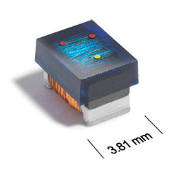
ST450RAB Series
Chip Inductors for Critical Applications
With inductance values up to 1000 μH, these are our highest inductance chip inductors.
Their ferrite core allows higher current ratings and lower DC resistance.
Specifications
Electrical specifications at 25°C.
| Part number 1 |
Inductance (µH)
2
(Tolerance: ±5%) |
Q typ 3 | SRF min (MHz) 4 | DCR max (Ω) 5 | Imax (mA) |
|---|---|---|---|---|---|
| ST450RAB123JLZ | 12 @ 2.5 MHz | 22 @ 790 kHz | 55 | 2.0 | 280 |
| ST450RAB153JLZ | 15 @ 2.5 MHz | 22 @ 790 kHz | 45 | 2.5 | 260 |
| ST450RAB183JLZ | 18 @ 2.5 MHz | 24 @ 790 kHz | 37 | 2.8 | 240 |
| ST450RAB223JLZ | 22 @ 2.5 MHz | 20 @ 790 kHz | 32 | 3.2 | 210 |
| ST450RAB273JLZ | 27 @ 2.5 MHz | 24 @ 790 kHz | 27 | 3.6 | 200 |
| ST450RAB333JLZ | 33 @ 2.5 MHz | 22 @ 790 kHz | 23 | 4.0 | 190 |
| ST450RAB393JLZ | 39 @ 2.5 MHz | 20 @ 790 kHz | 19 | 4.5 | 185 |
| ST450RAB473JLZ | 47 @ 2.5 MHz | 24 @ 790 kHz | 16 | 5.0 | 180 |
| ST450RAB563JLZ | 56 @ 2.5 MHz | 22 @ 790 kHz | 13 | 5.5 | 170 |
| ST450RAB683JLZ | 68 @ 2.5 MHz | 24 @ 790 kHz | 10 | 6.0 | 150 |
| ST450RAB823JLZ | 82 @ 2.5 MHz | 24 @ 790 kHz | 9 | 7.0 | 135 |
| ST450RAB104JLZ | 100 @ 2.5 MHz | 24 @ 790 kHz | 8.5 | 8.0 | 135 |
| ST450RAB124JLZ | 120 @ 790 kHz | 25 @ 790 kHz | 8.5 | 11.5 | 110 |
| ST450RAB154JLZ | 150 @ 790 kHz | 23 @ 790 kHz | 8.5 | 13.0 | 100 |
| ST450RAB184JLZ | 180 @ 790 kHz | 24 @ 790 kHz | 8 | 14.2 | 85 |
| ST450RAB224JLZ | 220 @ 790 kHz | 23 @ 790 kHz | 6 | 16.2 | 80 |
| ST450RAB274JLZ | 270 @ 790 kHz | 23 @ 790 kHz | 5 | 20.5 | 75 |
| ST450RAB334JLZ | 330 @ 790 kHz | 24 @ 790 kHz | 4.5 | 22.5 | 70 |
| ST450RAB394JLZ | 390 @ 790 kHz | 14 @ 250 kHz | 3.5 | 24.5 | 65 |
| ST450RAB474JLZ | 470 @ 790 kHz | 15 @ 250 kHz | 3 | 26.5 | 65 |
| ST450RAB564JLZ | 560 @ 790 kHz | 13 @ 250 kHz | 2 | 28.5 | 65 |
| ST450RAB684JLZ | 680 @ 790 kHz | 13 @ 250 kHz | 1.9 | 38.5 | 60 |
| ST450RAB824JLZ | 820 @ 790 kHz | 13 @ 250 kHz | 1.6 | 41.0 | 50 |
| ST450RAB105JLZ | 1000 @ 790 kHz | 15 @ 250 kHz | 1.5 | 44.0 | 50 |
Notes
- When ordering, please specify termination and testing codes: e.g. ST450RAB105JLZ.
- Inductance at 2.5 MHz measured using an Agilent/HP 4286A or equivalent and a Coilcraft SMD-A fixture with Coilcraft-provided correlation pieces. Inductance at 0.79 MHz measured using an Agilent/HP 4192A or equivalent and Coilcraft SMD-B test fixture.
- Q read at test frequency directly on an Agilent/HP 4395A impedance analyzer and an Agilent/HP 16193A test fixture or equivalents.
- SRF measured using an Agilent/HP 8753D network analyzer or equivalent and a Coilcraft SMD-D test fixture.
- DCR measured on a Cambridge Technology micro-ohmmeter or equivalent.
Termination:
- L = Silver-palladium-platinum glass frit.
- R = Tin over nickel over silver-platinum-glass frit. (Special order, added cost)
- S = Tin-lead (63/37) over silver-platinum-glass frit. (Special order, added cost)
- T = Tin-silver-copper (95.5/4/0.5) over silver-platinumglass frit. (Special order, added cost)
- P = Tin-lead (63/37) over tin over nickel over silver-platinum-glass frit. (Special order, added cost)
- Q = Tin-silver-copper (95.5/4/0.5) over tin over nickel over silver-platinum-glass frit. (Special order, added cost)
Testing:
- Z = Unscreened
- H = Group A screening per Coilcraft CP-SA-10001
Custom screening also available.
Environmental
Ambient temperature range:
–40°C to +85°C with Imax current.
Storage temperature range:
Component: –55°C to +100°C.
Tape and reel packaging: –55°C to +80°C.
Tape and reel packaging: –55°C to +80°C.
Maximum part temperature:
+100°C (ambient + temp rise).
Failures in Time (FIT) / Mean Time Between Failures (MTBF):
Performance curves
L vs Frequency

Q vs Frequency

Physical characteristics

| A max | B max | C max | D ref | E | F | G | H | I | J | |
|---|---|---|---|---|---|---|---|---|---|---|
| 0.195 | 0.150 | 0.135 | 0.070 | 0.100 | 0.025 | 0.128 | 0.120 | 0.045 | 0.118 | inches |
| 4,95 | 3,81 | 3,43 | 1,78 | 2,54 | 0,64 | 3,25 | 3,05 | 1,14 | 3,00 | mm |
General specification
Core Material:
Ferrite
Packaging:
600 per 7″ reel Plastic tape: 12 mm wide, 0.3 mm thick, 8 mm pocket spacing, 3.7 mm pocket depth.
Temperature coefficient of inductance:
+200 to +700 ppm/°C.
Soldering/Washing
Moisture Sensitivity Level (MSL):
1 (unlimited floor life at <30°C / 85% relative humidity).
Resistance to soldering heat:
Max three 40 second reflows at +260°C, parts cooled to room temperature between cycles.
Refer to Soldering Coilcraft Components before soldering.