Datasheet
3D Model
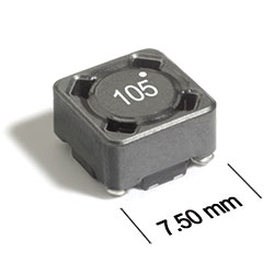
ST526PND Series
Coupled Inductors for Critical Applications
Tight coupling (k ≥ 0.97) and 200 V isolation make the ST526PND series of coupled inductors ideal for use in a variety of circuits including flyback, multi-output buck and SEPIC.
These inductors provide high inductance, high efficiency and excellent current handling in a rugged, low cost part.
They can also be used as two single inductors connected in series or parallel, as a common mode choke or as a 1:1 transformer.
They can also be used as two single inductors connected in series or parallel, as a common mode choke or as a 1:1 transformer.
Specifications
Electrical specifications at 25°C.
For Flyback Applications
| Part number 1 |
Inductance (µH)
2
(Tolerance: ±20%) |
DCR max (Ω) 3 |
Isolation Voltage (V) |
Leakage Inductance (µH) 5 |
|---|---|---|---|---|
| ST526PND252MLZ | 2.5 | 0.033 | 200 | 0.14 |
| ST526PND332MLZ | 3.3 | 0.037 | 200 | 0.090 |
| ST526PND472MLZ | 4.7 | 0.051 | 200 | 0.11 |
| ST526PND562MLZ | 5.6 | 0.063 | 200 | 0.090 |
| ST526PND682MLZ | 6.8 | 0.070 | 200 | 0.14 |
| ST526PND822MLZ | 8.2 | 0.075 | 200 | 0.25 |
| ST526PND103MLZ | 10 | 0.10 | 200 | 0.30 |
| ST526PND123MLZ | 12 | 0.12 | 200 | 0.36 |
| ST526PND153MLZ | 15 | 0.13 | 200 | 0.49 |
| ST526PND183MLZ | 18 | 0.17 | 200 | 0.16 |
| ST526PND223MLZ | 22 | 0.22 | 200 | 0.20 |
| ST526PND273MLZ | 27 | 0.25 | 200 | 0.20 |
| ST526PND333MLZ | 33 | 0.27 | 200 | 0.15 |
| ST526PND393MLZ | 39 | 0.38 | 200 | 0.70 |
| ST526PND473MLZ | 47 | 0.42 | 200 | 0.30 |
| ST526PND563MLZ | 56 | 0.46 | 200 | 0.51 |
| ST526PND683MLZ | 68 | 0.60 | 200 | 0.51 |
| ST526PND823MLZ | 82 | 0.68 | 200 | 1.2 |
| ST526PND104MLZ | 100 | 0.77 | 200 | 0.96 |
| ST526PND124MLZ | 120 | 1.0 | 200 | 0.61 |
| ST526PND154MLZ | 150 | 1.4 | 200 | 0.54 |
| ST526PND184MLZ | 180 | 1.5 | 200 | 0.75 |
| ST526PND224MLZ | 220 | 1.7 | 200 | 1.4 |
| ST526PND274MLZ | 270 | 2.4 | 200 | 1.6 |
| ST526PND334MLZ | 330 | 2.7 | 200 | 1.7 |
| ST526PND394MLZ | 390 | 3.1 | 200 | 4.7 |
| ST526PND474MLZ | 470 | 4.0 | 200 | 5.5 |
| ST526PND564MLZ | 560 | 4.4 | 200 | 4.9 |
| ST526PND684MLZ | 680 | 5.0 | 200 | 7.6 |
| ST526PND824MLZ | 820 | 6.8 | 200 | 8.0 |
| ST526PND105MLZ | 1000 | 7.8 | 200 | 8.7 |
For SEPIC Applications
| Part number 1 |
Inductance (µH)
2
(Tolerance: ±20%) |
DCR max (Ω) 3 | SRF Typ (MHz) 4 | Coupling coefficient |
Leakage Inductance (µH) 5 |
Isat (A) 6 | Irms (A) | |||
|---|---|---|---|---|---|---|---|---|---|---|
| 10% drop | 20% drop | 30% drop | both windings 7 | one winding 8 | ||||||
| ST526PND252MLZ | 2.5 | 0.033 | 55.0 | 0.97 | 0.14 | 6.0 | 6.2 | 6.3 | 2.17 | 3.06 |
| ST526PND332MLZ | 3.3 | 0.037 | 43.0 | 0.99 | 0.090 | 5.2 | 5.3 | 5.4 | 2.05 | 2.89 |
| ST526PND472MLZ | 4.7 | 0.051 | 35.0 | 0.99 | 0.11 | 4.1 | 4.3 | 4.6 | 1.74 | 2.46 |
| ST526PND562MLZ | 5.6 | 0.063 | 32.0 | 0.99 | 0.090 | 3.9 | 4.1 | 4.2 | 1.57 | 2.22 |
| ST526PND682MLZ | 6.8 | 0.070 | 30.0 | 0.99 | 0.14 | 3.7 | 3.8 | 3.9 | 1.49 | 2.10 |
| ST526PND822MLZ | 8.2 | 0.075 | 27.0 | 0.98 | 0.25 | 3.3 | 3.4 | 3.5 | 1.44 | 2.03 |
| ST526PND103MLZ | 10 | 0.10 | 22.0 | 0.98 | 0.30 | 2.8 | 2.9 | 3.0 | 1.24 | 1.76 |
| ST526PND123MLZ | 12 | 0.12 | 20.0 | 0.98 | 0.36 | 2.5 | 2.6 | 2.7 | 1.14 | 1.61 |
| ST526PND153MLZ | 15 | 0.13 | 18.0 | 0.98 | 0.49 | 2.2 | 2.3 | 2.4 | 1.09 | 1.54 |
| ST526PND183MLZ | 18 | 0.17 | 15.0 | >0.99 | 0.16 | 2.0 | 2.2 | 2.3 | 0.95 | 1.35 |
| ST526PND223MLZ | 22 | 0.22 | 13.5 | >0.99 | 0.20 | 1.9 | 2.0 | 2.1 | 0.84 | 1.19 |
| ST526PND273MLZ | 27 | 0.25 | 12.0 | >0.99 | 0.20 | 1.7 | 1.8 | 1.9 | 0.79 | 1.11 |
| ST526PND333MLZ | 33 | 0.27 | 11.0 | >0.99 | 0.15 | 1.5 | 1.6 | 1.7 | 0.76 | 1.07 |
| ST526PND393MLZ | 39 | 0.38 | 10.0 | 0.99 | 0.70 | 1.3 | 1.4 | 1.5 | 0.64 | 0.90 |
| ST526PND473MLZ | 47 | 0.42 | 9.5 | >0.99 | 0.30 | 1.2 | 1.3 | 1.4 | 0.61 | 0.86 |
| ST526PND563MLZ | 56 | 0.46 | 8.7 | >0.99 | 0.51 | 1.1 | 1.2 | 1.3 | 0.58 | 0.82 |
| ST526PND683MLZ | 68 | 0.60 | 7.3 | >0.99 | 0.51 | 1.0 | 1.1 | 1.2 | 0.51 | 0.72 |
| ST526PND823MLZ | 82 | 0.68 | 6.2 | 0.99 | 1.2 | 0.90 | 1.0 | 1.1 | 0.48 | 0.67 |
| ST526PND104MLZ | 100 | 0.77 | 5.5 | >0.99 | 0.96 | 0.80 | 0.92 | 0.98 | 0.45 | 0.63 |
| ST526PND124MLZ | 120 | 1.0 | 4.5 | >0.99 | 0.61 | 0.70 | 0.80 | 0.90 | 0.39 | 0.55 |
| ST526PND154MLZ | 150 | 1.4 | 4.0 | >0.99 | 0.54 | 0.65 | 0.76 | 0.80 | 0.34 | 0.48 |
| ST526PND184MLZ | 180 | 1.5 | 3.8 | >0.99 | 0.75 | 0.62 | 0.66 | 0.73 | 0.32 | 0.45 |
| ST526PND224MLZ | 220 | 1.7 | 3.5 | >0.99 | 1.4 | 0.59 | 0.62 | 0.66 | 0.30 | 0.42 |
| ST526PND274MLZ | 270 | 2.4 | 3.3 | >0.99 | 1.6 | 0.55 | 0.57 | 0.60 | 0.25 | 0.36 |
| ST526PND334MLZ | 330 | 2.7 | 3.0 | >0.99 | 1.7 | 0.49 | 0.52 | 0.54 | 0.24 | 0.34 |
| ST526PND394MLZ | 390 | 3.1 | 2.8 | 0.99 | 4.7 | 0.45 | 0.47 | 0.50 | 0.23 | 0.32 |
| ST526PND474MLZ | 470 | 4.0 | 2.6 | 0.99 | 5.5 | 0.41 | 0.43 | 0.46 | 0.20 | 0.28 |
| ST526PND564MLZ | 560 | 4.4 | 2.5 | >0.99 | 4.9 | 0.38 | 0.40 | 0.42 | 0.19 | 0.26 |
| ST526PND684MLZ | 680 | 5.0 | 2.3 | 0.99 | 7.6 | 0.36 | 0.37 | 0.38 | 0.18 | 0.25 |
| ST526PND824MLZ | 820 | 6.8 | 2.2 | >0.99 | 8.0 | 0.30 | 0.32 | 0.35 | 0.15 | 0.21 |
| ST526PND105MLZ | 1000 | 7.8 | 2.0 | >0.99 | 8.7 | 0.27 | 0.29 | 0.31 | 0.14 | 0.20 |
Notes
- When ordering, please specify termination and screening codes: e.g. ST526PND105MLZ.
- Inductance shown for each winding, measured at 100 kHz, 0.1 Vrms, 0 Adc on an Agilent/HP 4284A LCR meter or equivalent. When leads are connected in parallel, inductance is the same value. When leads are connected in series, inductance is four times the value.
- DCR is for each winding. When leads are connected in parallel, DCR is half the value. When leads are connected in series, DCR is twice the value.
- SRF measured using an Agilent/HP 4191A or equivalent. When leads are connected in parallel, SRF is the same value.
- Leakage inductance is for L1 and is measured with L2 shorted.
- DC current at 25°C that causes the specified inductance drop from its value without current It is the sum of the current flowing in both windings.
- Equal current when applied to each winding simultaneously that causes a 40°C temperature rise from 25°C ambient. This information is for reference only and does not represent absolute maximum ratings.
- Maximum current when applied to one winding that causes a 40°C temperature rise from 25°C ambient. This information is for reference only and does not represent absolute maximum ratings.
Refer to Doc 639 “Selecting Coupled Inductors for SEPIC Applications.”
Termination:
- L = Matte tin over nickel over phos bronze.
- T = Tin-silver-copper (95.5/4/0.5). (Special order, added cost)
- S = Tin-lead (63/37). (Special order, added cost)
Screening:
- Z = Unscreened
- Y = Unscreened (SLDC Option A)
- W = Unscreened (SLDC Option B)
- H = Group A screening per Coilcraft CP-SA-10001
- G = Coilcraft CP-SA-10001 Group A (SLDC Option A)
- D = Coilcraft CP-SA-10001 Group A (SLDC Option B)
Custom screening also available.
Environmental
Ambient temperature range:
–40°C to +85°C with Irms current.
Storage temperature range:
Component: –55°C to +125°C.
Tape and reel packaging: –55°C to +80°C.
Tape and reel packaging: –55°C to +80°C.
Maximum part temperature:
+125°C (ambient + temp rise).
Failures in Time (FIT) / Mean Time Between Failures (MTBF):
Performance curves
Typical L vs Current

Typical L vs Frequency

Schematics


General specification
Core Material:
Ferrite
Weight:
0.76 – 0.87g
Winding to Winding Isolation:
200 Vrms
Soldering/Washing
Moisture Sensitivity Level (MSL):
1 (unlimited floor life at <30°C / 85% relative humidity).
Resistance to soldering heat:
Max three 40 second reflows at +260°C, parts cooled to room temperature between cycles.
Refer to Soldering Coilcraft Components before soldering.