Datasheet
3D Model
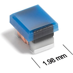
AR336RAB Series
AR336RAB Series features high temperature materials allowing operation in ambient temperatures up to 155°C.
- Passes NASA low outgassing specifications.
- Standard tin-lead (Sn-Pb) terminations ensure the best possible board adhesion. Note: Nickel barrier termination (tin-lead over tin over nickel over silver-platinumglass frit, termination code P) is recommended for hand soldering applications.
Specifications
Electrical specifications at 25°C.
| Part number 1 | Inductance (µH) 2 | Tolerance (%) 3 | Q min 4 | SRF typ (MHz) 5 | DCR max (Ω) 6 | Imax (A) |
|---|---|---|---|---|---|---|
| AR336RAB78N_PZ | 0.078 @ 7.9 MHz | 5,2 | 19 @ 7.9 MHz | 1300 | 0.042 | 800 |
| AR336RAB111_PZ | 0.11 @ 7.9 MHz | 5,2 | 19 @ 7.9 MHz | 1250 | 0.055 | 800 |
| AR336RAB181_PZ | 0.18 @ 7.9 MHz | 5,2 | 20 @ 7.9 MHz | 900 | 0.10 | 800 |
| AR336RAB241_PZ | 0.24 @ 7.9 MHz | 5,2 | 18 @ 7.9 MHz | 780 | 0.21 | 590 |
| AR336RAB271_PZ | 0.27 @ 7.9 MHz | 5,2 | 18 @ 7.9 MHz | 620 | 0.32 | 480 |
| AR336RAB471_PZ | 0.47 @ 7.9 MHz | 5,2 | 20 @ 7.9 MHz | 510 | 0.30 | 510 |
| AR336RAB561_PZ | 0.56 @ 7.9 MHz | 5,2 | 20 @ 7.9 MHz | 580 | 0.46 | 450 |
| AR336RAB681_PZ | 0.68 @ 7.9 MHz | 5,2 | 25 @ 7.9 MHz | 530 | 0.48 | 430 |
| AR336RAB102_PZ | 1.0 @ 7.9 MHz | 5,2 | 20 @ 7.9 MHz | 340 | 0.69 | 280 |
| AR336RAB122_PZ | 1.2 @ 7.9 MHz | 5,2 | 25 @ 7.9 MHz | 310 | 1.3 | 270 |
| AR336RAB152_PZ | 1.5 @ 7.9 MHz | 5,2 | 25 @ 7.9 MHz | 320 | 1.1 | 260 |
| AR336RAB182_PZ | 1.8 @ 7.9 MHz | 5,2 | 30 @ 7.9 MHz | 270 | 1.3 | 250 |
| AR336RAB222_PZ | 2.2 @ 7.9 MHz | 5,2 | 30 @ 7.9 MHz | 110 | 1.4 | 240 |
| AR336RAB272_PZ | 2.7 @ 7.9 MHz | 5,2 | 30 @ 7.9 MHz | 210 | 1.5 | 230 |
| AR336RAB332_PZ | 3.3 @ 7.9 MHz | 5,2 | 30 @ 7.9 MHz | 85.0 | 1.6 | 220 |
| AR336RAB392_PZ | 3.9 @ 7.9 MHz | 5,2 | 30 @ 7.9 MHz | 55.0 | 1.7 | 210 |
| AR336RAB472_PZ | 4.7 @ 7.9 MHz | 5,2 | 30 @ 7.9 MHz | 55.0 | 1.9 | 200 |
| AR336RAB562_PZ | 5.6 @ 7.9 MHz | 5,2 | 20 @ 7.9 MHz | 40.0 | 2.1 | 190 |
| AR336RAB682_PZ | 6.8 @ 7.9 MHz | 5,2 | 25 @ 7.9 MHz | 33.0 | 2.4 | 180 |
| AR336RAB752_PZ | 7.5 @ 7.9 MHz | 5,2 | 25 @ 7.9 MHz | 27.0 | 2.4 | 180 |
| AR336RAB822_PZ | 8.2 @ 2.5 MHz | 5,2 | 24 @ 2.5 MHz | 24.0 | 2.6 | 170 |
| AR336RAB872_PZ | 8.7 @ 2.5 MHz | 5,2 | 24 @ 2.5 MHz | 24.0 | 2.6 | 170 |
| AR336RAB103_PZ | 10 @ 2.5 MHz | 5,2 | 21 @ 2.5 MHz | 19.0 | 3.8 | 160 |
| AR336RAB123_PZ | 12 @ 2.5 MHz | 5,2 | 22 @ 2.5 MHz | 17.0 | 3.9 | 160 |
| AR336RAB153_PZ | 15 @ 2.5 MHz | 5,2 | 21 @ 2.5 MHz | 14.0 | 5.3 | 130 |
| AR336RAB183_PZ | 18 @ 2.5 MHz | 5,2 | 14 @ 2.5 MHz | 13.0 | 5.8 | 120 |
| AR336RAB223_PZ | 22 @ 2.5 MHz | 5,2 | 21 @ 2.5 MHz | 11.0 | 6.5 | 110 |
| AR336RAB273_PZ | 27 @ 2.5 MHz | 5,2 | 20 @ 2.5 MHz | 10.0 | 11.0 | 80.0 |
| AR336RAB333_PZ | 33 @ 2.5 MHz | 5,2 | 22 @ 2.5 MHz | 16.0 | 12.3 | 70.0 |
| AR336RAB393_PZ | 39 @ 2.5 MHz | 5,2 | 28 @ 2.5 MHz | 13.0 | 13.6 | 60.0 |
| AR336RAB473_PZ | 47 @ 2.5 MHz | 5,2 | 22 @ 2.5 MHz | 9.0 | 14.1 | 50.0 |
| AR336RAB503_PZ | 50 @ 2.5 MHz | 5,2 | 22 @ 2.5 MHz | 8.0 | 14.6 | 40.0 |
| AR336RAB603_PZ | 60 @ 2.5 MHz | 5,2 | 10 @ 2.5 MHz | 7.0 | 15.0 | 30.0 |
Notes
- When ordering, specify tolerance, termination and screening codes: e.g. AR336RAB603JPZ
- Inductance measured using a Coilcraft SMD-A fixture in an Agilent/ HP 4286A impedance analyzer with Coilcraft-provided correlation pieces.
- Tolerances in bold are stocked for immediate shipment.
- Q measured on an Agilent/HP 4291A with an Agilent/HP 16193 test fixture.
- SRF measured using an Agilent/HP 8753D network analyzer with a Coilcraft SMD-D test fixture.
- DCR measured on a Cambridge Technology Micro-ohmmeter.
Tolerance:
G = 2% J = 5%Termination:
- P = Tin-lead (63/37) over tin over nickel over silverplatinum-glass frit
- C = Tin-lead (63/37) over gold over nickel over moly-mag
- A = Gold over nickel over moly-mag
Screening:
- Z = Unscreened
- H = Coilcraft CP-SA-10001 Group A
- 1 = EEE-INST-002 (Family 3) Level 1
- 2 = EEE-INST-002 (Family 3) Level 2
- 3 = EEE-INST-002 (Family 3) Level 3
- 4 = MIL-STD-981 (Family 50) Class B
- 5 = MIL-STD-981 (Family 50) Class S
- F = ESCC3201 (F4 operational life performed at 90°C)
- Screening performed to the document’s latest revision.
- Lot qualification (Group B) available.
- Custom testing also available.
- Country of origin restrictions available; prefix options G or F.
Environmental
Ambient temperature range:
–55°C to +125°C with Imax current.
Storage temperature range:
Component: –55°C to +155°C
Tape and reel packaging: –55°C to +80°C
Tape and reel packaging: –55°C to +80°C
Maximum part temperature:
+155°C (ambient + temp rise).
Failures in Time (FIT) / Mean Time Between Failures (MTBF):
Performance curves
L vs Frequency

Q vs Frequency

Physical characteristics

| A max | B max | C max | D ref | E | F | G | H | I | J | |
|---|---|---|---|---|---|---|---|---|---|---|
| 0.09 | 0.075 | 0.063 | 0.020 | 0.050 | 0.020 | 0.040 | 0.070 | 0.040 | 0.030 | inches |
| 2,29 | 1,91 | 1,60 | 0,51 | 1,27 | 0,51 | 1,02 | 1,78 | 1,02 | 0,76 | mm |
Dimensions are before solder application. For maximum overall dimensions including solder, add 0.0025 in / 0.064 mm to E and 0.006 in / 0.15 mm to A and C.
General specification
Core Material:
Ceramic/Ferrite
Weight:
14 – 20 mg
Packaging:
2000/7″reel; 7500/13″reel; Plastic tape: 8 mm wide, 0.23 mm thick, 4 mm pocket spacing, 1.6 mm pocket depth
Temperature coefficient of inductance:
+100 to +250 ppm/°C
Soldering/Washing
Moisture Sensitivity Level (MSL):
1 (unlimited floor life at <30°C / 85% relative humidity)
Resistance to soldering heat:
Max three 40 second reflows at +260°C, parts cooled to room temperature between cycles
Refer to Soldering Coilcraft Components before soldering.
PCB Washing:
Tested to MIL-STD-202 Method 215 plus an additional aqueous wash. More info