Datasheet
3D Models
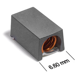
AT536RAT Series
200°C Air Core Inductors
AT536RAT Series features high Q over a wide range of frequencies.
- Special materials allow operation in ambient temperatures as low as –60°C and up to 200°C.
- Passes NASA low outgassing specifications.
Specifications
Electrical specifications at 25°C.
| Part number 1 | Turns | Inductance (nH) 2 | Tolerance (%) |
Q min
@ 50.0 MHz 3 |
SRF min (GHz) 4 | DCR max (mΩ) 5 | Imax (A) |
|---|---|---|---|---|---|---|---|
| AT536RAT90N_S_ | 9 | 90 | 5,2 | 95 | 1.140 | 15 | 3.5 |
| AT536RATR11_S_ | 10 | 111 | 5,2 | 87 | 1.020 | 15 | 3.5 |
| AT536RATR13_S_ | 11 | 130 | 5,2 | 87 | 0.900 | 20 | 3.0 |
| AT536RATR17_S_ | 12 | 169 | 5,2 | 95 | 0.875 | 25 | 3.0 |
| AT536RATR21_S_ | 13 | 206 | 5,2 | 95 | 0.800 | 30 | 3.0 |
| AT536RATR22_S_ | 14 | 222 | 5,2 | 92 | 0.730 | 35 | 3.0 |
| AT536RATR25_S_ | 15 | 246 | 5,2 | 95 | 0.685 | 35 | 3.0 |
| AT536RATR31_S_ | 16 | 307 | 5,2 | 95 | 0.660 | 35 | 3.0 |
| AT536RATR38_S_ | 17 | 380 | 5,2 | 95 | 0.590 | 50 | 2.5 |
| AT536RATR42_S_ | 18 | 422 | 5,2 | 95 | 0.540 | 60 | 2.5 |
| AT536RATR49_S_ | 19 | 491 | 5,2 | 95 | 0.535 | 65 | 2.0 |
| AT536RATR54_S_ | 20 | 538 | 5,2 | 87 | 0.490 | 90 | 2.0 |
Notes
- When ordering, specify tolerance and screening codes: e.g. AT536RATR54GSZ.
- Inductance measured at 50 MHz on an Agilent/HP 4286A or equivalent with a Coilcraft SMD-A test fixture and correlation.
- Q measured at 50 MHz on an Agilent/HP 4291A or equivalent with a 16193A test fixture or equivalent.
- SRF measured on an Agilent/HP 8753ES or equivalent with a Coilcraft CCF1268 test fixture.
- DCR measured on a Keithley 580 Micro-Ohmmeter or equivalent.
Tolerance:
- G = 2%
- J = 5%
Screening:
- Z = Unscreened
- H = Group A screening per Coilcraft CP-SA-10001
- F = Screening per ESCC 3201
- 1 = EEE-INST-002 (Family 3) Level 1
- 2 = EEE-INST-002 (Family 3) Level 2
- 3 = EEE-INST-002 (Family 3) Level 3
- 4 = MIL-STD-981 (Family 50) Class B
- 5 = MIL-STD-981 (Family 50) Class S
- Screening performed to the document’s latest revision.
- Screening not available for parts with 2% tolerance.
- Testing is performed using 155°C as max component temperature.
- Lot qualification (Group B) available.
- Testing T and U have been replaced with more detailed codes 4, 5, and 1, 2, 3, respectively. Codes T and U can still be used, if necessary. Custom testing also available.
- Country of origin restrictions available; prefix option G.
Environmental
Ambient temperature range:
–60°C to +150°C with Imax current.
Storage temperature range:
Component: –60°C to +200°C.
Tape and reel packaging: –55°C to +80°C.
Tape and reel packaging: –55°C to +80°C.
Maximum part temperature:
+200°C (ambient + temp rise).
Failures in Time (FIT) / Mean Time Between Failures (MTBF):
Performance curves
Typical L vs Frequency

Typical Q vs Frequency


General specification
Packaging:
800 per 13″ reel Plastic tape: 24 mm wide, 0.3 mm thick, 12 mm pocket spacing, 6.1 mm pocket depth.
Temperature coefficient of inductance:
+5 to +70 ppm/°C.
Soldering/Washing
Moisture Sensitivity Level (MSL):
1 (unlimited floor life at <30°C / 85% relative humidity).
Resistance to soldering heat:
Max three 40 second reflows at +260°C, parts cooled to room temperature between cycles.
Refer to Soldering Coilcraft Components before soldering.