Datasheet
3D Model
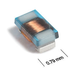
ST235RAP Series
Chip Inductors for Critical Applications
ST235RAP Series chip inductors feature higher inductance values than other 0402 ceramic chip inductors.
- Higher inductance values than other 0402 ceramic chip inductors.
- 28 inductance values from 43 nH to 820 nH.
- Matte tin over nickel over silver-platinum-glass frit terminations. Other terminations available at additional cost.
Specifications
Electrical specifications at 25°C.
| Part number 1 |
Inductance (nH)
2
(Tolerance: ± 5%) |
Q min 3 | SRF min (MHz) 4 | DCR max (Ω) 5 | Imax (mA) |
|---|---|---|---|---|---|
| ST235RAP430JRZ | 43 | 21 @ 250 MHz | 2900 | 0.75 | 250 |
| ST235RAP510JRZ | 51 | 21 @ 250 MHz | 2700 | 0.85 | 240 |
| ST235RAP560JRZ | 56 | 21 @ 250 MHz | 2600 | 0.90 | 240 |
| ST235RAP680JRZ | 68 | 11 @ 100 MHz | 760 | 0.85 | 230 |
| ST235RAP720JRZ | 72 | 12 @ 100 MHz | 720 | 0.90 | 210 |
| ST235RAP750JRZ | 75 | 11 @ 100 MHz | 700 | 0.90 | 210 |
| ST235RAP820JRZ | 82 | 11 @ 100 MHz | 680 | 0.95 | 210 |
| ST235RAP900JRZ | 90 | 11 @ 100 MHz | 560 | 1.00 | 210 |
| ST235RAP910JRZ | 91 | 10 @ 100 MHz | 560 | 1.00 | 200 |
| ST235RAP101JRZ | 100 | 10 @ 100 MHz | 680 | 1.05 | 200 |
| ST235RAP111JRZ | 110 | 10 @ 100 MHz | 670 | 1.10 | 190 |
| ST235RAP121JRZ | 120 | 11 @ 100 MHz | 530 | 1.15 | 190 |
| ST235RAP151JRZ | 150 | 10 @ 100 MHz | 640 | 1.35 | 180 |
| ST235RAP181JRZ | 180 | 9 @ 100 MHz | 510 | 1.45 | 170 |
| ST235RAP201JRZ | 200 | 9 @ 100 MHz | 510 | 1.55 | 170 |
| ST235RAP221JRZ | 220 | 9 @ 100 MHz | 540 | 1.70 | 170 |
| ST235RAP271JRZ | 270 | 8 @ 25.0 MHz | 470 | 1.95 | 160 |
| ST235RAP301JRZ | 300 | 8 @ 25.0 MHz | 480 | 2.15 | 160 |
| ST235RAP331JRZ | 330 | 8 @ 25.0 MHz | 410 | 2.23 | 150 |
| ST235RAP361JRZ | 360 | 8 @ 25.0 MHz | 388 | 2.36 | 140 |
| ST235RAP391JRZ | 390 | 8 @ 25.0 MHz | 208 | 2.35 | 140 |
| ST235RAP471JRZ | 470 | 8 @ 25.0 MHz | 176 | 2.67 | 130 |
| ST235RAP511JRZ | 510 | 9 @ 25.0 MHz | 360 | 3.50 | 110 |
| ST235RAP561JRZ | 560 | 9 @ 25.0 MHz | 336 | 3.70 | 110 |
| ST235RAP601JRZ | 600 | 9 @ 25.0 MHz | 352 | 3.78 | 100 |
| ST235RAP681JRZ | 680 | 10 @ 25.0 MHz | 304 | 5.15 | 90 |
| ST235RAP741JRZ | 740 | 9 @ 25.0 MHz | 132 | 5.45 | 80 |
| ST235RAP821JRZ | 820 | 10 @ 25.0 MHz | 308 | 5.85 | 70 |
Notes
- When ordering, please specify termination and screening codes: e.g. ST235RAP821JRZ.
- Inductance measured using a Coilcraft SMD-F test fixture and Coilcraft-provided correlation pieces with an Agilent/HP 4286A impedance analyzer or equivalent.
- Q measured using an Agilent/HP 4291A with an Agilent/HP 16197A test fixture or equivalents.
- SRF measured using an Agilent/HP 8753ES network analyzer and a Coilcraft CCF1232 test fixture.
- DCR measured on Keithley 580 micro-ohmmeter and a Coilcraft CCF1010 test fixture.
Termination:
- R = Matte tin over nickel over silver-platinum-glass frit.
- Q = Tin-silver-copper (95.5/4/0.5). (Special order, added cost)
- P = Tin-lead (63/37). (Special order, added cost)
Testing:
- Z = Unscreened
- H = Group A screening per Coilcraft CP-SA-10001
Environmental
Ambient temperature range:
–40°C to +125°C with Irms current.
Storage temperature range:
Component: –55°C to +140°C.
Tape and reel packaging: –55°C to +80°C.
Tape and reel packaging: –55°C to +80°C.
Maximum part temperature:
+140°C (ambient + temp rise).
Failures in Time (FIT) / Mean Time Between Failures (MTBF):
Performance curves
Typical Impedance vs Frequency

Typical L vs Frequency

Typical Q vs Frequency


General specification
Core Material:
Ceramic
Weight:
0.7 – 1.3 mg
Packaging:
2000 per 7″ reel. Paper tape: 8 mm wide, 0.66 mm thick, 2 mm pocket spacing.
Temperature coefficient of inductance:
+25 to +150 ppm/°C.
Soldering/Washing
Moisture Sensitivity Level (MSL):
1 (unlimited floor life at <30°C / 85% relative humidity).
Resistance to soldering heat:
Max three 40 second reflows at +260°C, parts cooled to room temperature between cycles.
Refer to Soldering Coilcraft Components before soldering.