Datasheet
3D Model
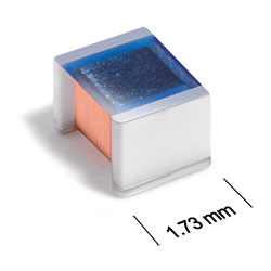
ST336RAG Series
Chip Inductors for Critical Applications
ST336RAG Series features exceptional Q values, even at high frequencies.
- Tight tolerances – 2% for most
- Wirewound construction for highest possible self resonance – up to 9.5 GHz.
- Matte tin over nickel over silver-platinum-glass frit. Other terminations available at additional cost.
Specifications
Electrical specifications at 25°C.
| Part number 1 | Inductance (nH) 2 | Tolerance (%) 3 | Q typ 4 | SRF typ (MHz) 5 | DCR max (Ω) 6 | Imax (mA) 7 |
|---|---|---|---|---|---|---|
| ST336RAG2N6JR_ | 2.6 @ 250 MHz | 5 | 100 @ 1500 MHz | 9500 | 0.015 | 800 |
| ST336RAG6N2JR_ | 6.2 @ 250 MHz | 5 | 104 @ 1000 MHz | 7200 | 0.027 | 800 |
| ST336RAG6N8JR_ | 6.8 @ 250 MHz | 5 | 90 @ 1000 MHz | 6000 | 0.066 | 800 |
| ST336RAG11N_R_ | 11 @ 250 MHz | 5,2 | 93 @ 500 MHz | 4750 | 0.039 | 800 |
| ST336RAG12N_R_ | 12 @ 250 MHz | 5,2 | 91 @ 500 MHz | 4425 | 0.039 | 800 |
| ST336RAG13N_R_ | 13 @ 250 MHz | 5,2 | 91 @ 500 MHz | 4100 | 0.039 | 800 |
| ST336RAG15N_R_ | 15 @ 250 MHz | 5,2 | 90 @ 500 MHz | 3100 | 0.066 | 800 |
| ST336RAG18N_R_ | 18 @ 250 MHz | 5,2 | 95 @ 500 MHz | 3650 | 0.050 | 800 |
| ST336RAG27N_R_ | 27 @ 250 MHz | 5,2 | 120 @ 500 MHz | 2830 | 0.083 | 800 |
| ST336RAG33N_R_ | 33 @ 250 MHz | 5,2 | 100 @ 500 MHz | 2410 | 0.087 | 800 |
| ST336RAG47N_R_ | 47 @ 200 MHz | 5,2 | 105 @ 500 MHz | 2170 | 0.093 | 800 |
| ST336RAG50N_R_ | 50 @ 200 MHz | 5,2 | 115 @ 500 MHz | 2010 | 0.122 | 800 |
| ST336RAG56N_R_ | 56 @ 200 MHz | 5,2 | 100 @ 500 MHz | 1815 | 0.122 | 800 |
| ST336RAG75N_R_ | 75 @ 200 MHz | 5,2 | 114 @ 500 MHz | 1685 | 0.168 | 720 |
| ST336RAG82N_R_ | 82 @ 150 MHz | 5,2 | 103 @ 500 MHz | 1525 | 0.168 | 720 |
| ST336RAG101_R_ | 100 @ 150 MHz | 5,2 | 100 @ 500 MHz | 1400 | 0.220 | 690 |
| ST336RAG121_R_ | 120 @ 150 MHz | 5,2 | 80 @ 250 MHz | 1265 | 0.293 | 600 |
| ST336RAG151_R_ | 150 @ 100 MHz | 5,2 | 80 @ 250 MHz | 1150 | 0.288 | 590 |
| ST336RAG181_R_ | 180 @ 100 MHz | 5,2 | 77 @ 250 MHz | 1025 | 0.374 | 520 |
| ST336RAG201_R_ | 200 @ 100 MHz | 5,2 | 75 @ 250 MHz | 950 | 0.400 | 520 |
| ST336RAG221_R_ | 220 @ 100 MHz | 5,2 | 75 @ 250 MHz | 930 | 0.426 | 500 |
| ST336RAG251_R_ | 251 @ 100 MHz | 5,2 | 74 @ 250 MHz | 873 | 0.564 | 440 |
| ST336RAG271_R_ | 270 @ 100 MHz | 5,2 | 75 @ 100 MHz | 830 | 0.754 | 340 |
| ST336RAG291_R_ | 291 @ 100 MHz | 5,2 | 54 @ 100 MHz | 840 | 0.804 | 340 |
| ST336RAG311_R_ | 310 @ 100 MHz | 5,2 | 54 @ 100 MHz | 820 | 0.824 | 340 |
| ST336RAG331_R_ | 330 @ 100 MHz | 5,2 | 54 @ 100 MHz | 770 | 1.004 | 310 |
| ST336RAG391_R_ | 390 @ 100 MHz | 5,2 | 52 @ 100 MHz | 700 | 1.110 | 280 |
| ST336RAG471_R_ | 470 @ 50.0 MHz | 5,2 | 52 @ 100 MHz | 640 | 1.559 | 250 |
| ST336RAG561_R_ | 560 @ 25.0 MHz | 5,2 | 46 @ 100 MHz | 550 | 2.067 | 210 |
| ST336RAG681_R_ | 680 @ 25.0 MHz | 5,2 | 46 @ 100 MHz | 535 | 2.355 | 180 |
| ST336RAG821_R_ | 820 @ 25.0 MHz | 5,2 | 50 @ 100 MHz | 485 | 3.945 | 150 |
Notes
- When ordering, specify tolerance, termination and testing codes: e.g. ST336RAG821JRZ.
- Inductance measured using a Coilcraft SMD-A fixture in an Agilent/ HP 4286A impedance analyzer with Coilcraft-provided correlation pieces.
- Tolerances in bold are stocked for immediate shipment.
- Q measured using an Agilent/HP 4291A with an Agilent/HP 16193 test fixture.
- SRF measured using an Agilent/HP 8720D network analyzer and a Coilcraft SMD -D test fixture.
- DCR measured on a Cambridge Technology micro-ohmmeter and a Coilcraft CCF858 test fixture.
- Current that causes a 15°C temperature rise from 25°C ambient. This information is for reference only and does not represent absolute maximum ratings.
Tolerance:
- G = 2%
- J = 5%
Termination:
- R = Matte tin over nickel over silver-platinum-glass frit.
- Q = Tin-silver-copper (95.5/4/0.5) over tin. (Special order, added cost)
- P = non-RoHS tin-lead (63/37) over tin. (Special order, added cost)
Testing:
- Z = Unscreened
- H = Group A screening per Coilcraft CP-SA-10001
Custom screening also available.
Environmental
Ambient temperature range:
–40°C to +125°C with Irms current
Storage temperature range:
Component: –55°C to +140°C
Tape and reel packaging: –40°C to +80°C
Tape and reel packaging: –40°C to +80°C
Maximum part temperature:
+140°C (ambient + temp rise)
Failures in Time (FIT) / Mean Time Between Failures (MTBF):
Performance curves
L vs Frequency

Q vs Frequency


General specification
Core Material:
Ceramic
Weight:
9.5 – 12.5 mg
Packaging:
2000/7″ reel; 7500/13″ reel. Plastic tape: 8 mm wide, 0.23 mm thick, 4 mm pocket spacing, 1.65 mm pocket depth.
Temperature coefficient of inductance:
+100 to +250 ppm/°C
Soldering/Washing
Moisture Sensitivity Level (MSL):
1 (unlimited floor life at <30°C / 85% relative humidity)
Resistance to soldering heat:
Max three 40 second reflows at +260°C, parts cooled to room temperature between cycles.
Refer to Soldering Coilcraft Components before soldering.
PCB Washing:
Tested to MIL-STD-202 Method 215 plus an additional aqueous wash. See Doc787_PCB_Washing.pdf.