Datasheet
3D Model
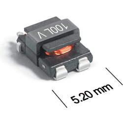
ST511TCB Series
Current Sense Transformers
ST511TCB Series offers very low primary DC resistance.
- Small surface mount current sensors.
- Sensed current up to 20 A; Frequency range up to 1 MHz.
- 500 Vrms, one minute isolation (hipot) between windings.
- Designed for:
- Continuous AC current monitoring in switched-mode power supply
- Overload and short-circuit protection
- Current measurement in traction motor and battery management systems in conventional and xEV (EV, HEV, FCEV) vehicles.
- Can also be used in 48 V vehicle electrical systems.
- Tin-silver-copper over tin over nickel over phos bronze terminations,
Specifications
Electrical specifications at 25°C.
| Part number 1 |
Inductance min (mH) 2 |
DCR max (Ω) | Turns Ratio |
Volt-time product (V-µs) 3 |
Frequency (kHz) | Sensed current max (A) 4 |
Terminating resistance RT (Ω) 5 |
Isolation Voltage (Vrms) |
|
|---|---|---|---|---|---|---|---|---|---|
| pri | sec | Pri1 : Sec1 | |||||||
| ST511TCB1020L_ | 0.053 | 0.0015 | 0.4200 | 1 : 20 | 6.4 | 78 — 1000 | 20.0 | 1.0 | 500 |
| ST511TCB1050L_ | 0.333 | 0.0015 | 2.7600 | 1 : 50 | 16 | 31 — 1000 | 20.0 | 2.5 | 500 |
| ST511TCB1070L_ | 0.652 | 0.0015 | 5.0400 | 1 : 70 | 22.4 | 22 — 1000 | 20.0 | 3.5 | 500 |
| ST511TCB1100L_ | 1.330 | 0.0015 | 10.6800 | 1 : 100 | 32 | 16 — 1000 | 20.0 | 5.0 | 500 |
| ST511TCB1150L_ | 2.993 | 0.0015 | 22.3000 | 1 : 150 | 48 | 10 — 1000 | 20.0 | 7.5 | 500 |
Notes
- When ordering, please specify screening code: e.g. ST511TCB1150LZ.
- Inductance measured between secondary pins at 100 kHz, 0.1 Vrms, 0 Adc.
- Volt-time product is for the secondary, between pin 1 and 2.
- Primary current of 20 A causes less than 25°C temperature rise from 25°C ambient. Higher current causes a greater temperature rise (see Temperature Rise vs Current curve).
- Terminating resistance (RT) value is based on 1 Volt output with 20 Amps flowing through the primary. Varying terminating resistance increases or decreases output Voltage/Ampere according to the following equation: RT = Vout × Nsec/Iin.
Screening:
- Z = Unscreened
- H = Group A screening per Coilcraft CP-SA-10001
- Screening performed to the document’s latest revision.
- Lot qualification (Group B) available.
- Custom testing also available.
- Country of origin restrictions available; prefix option G
Environmental
Ambient temperature range:
–40°C to +125°C.
Storage temperature range:
Component: –55°C to +165°C.
Tape and reel packaging: –40°C to +80°C.
Tape and reel packaging: –40°C to +80°C.
Maximum part temperature:
+165°C (ambient + temp rise).
Failures in Time (FIT) / Mean Time Between Failures (MTBF):
Performance curves
Temperature Rise vs Current

Schematics


General specification
Core Material:
Ferrite
Weight:
0.16 g
Packaging:
600/7″ reel; 2500/13″ reel Plastic tape: 16 mm wide, 0.35 mm thick, 8 mm pocket spacing, 3.0 mm pocket depth.
Soldering/Washing
Moisture Sensitivity Level (MSL):
1 (unlimited floor life at <30°C / 85% relative humidity).
Resistance to soldering heat:
Max three 40 second reflows at +260°C, parts cooled to room temperature between cycles.
Refer to Soldering Coilcraft Components before soldering.
PCB Washing:
Tested to MIL-STD-202 Method 215 plus an additional aqueous wash. See Doc787_PCB_Washing.pdf.