Datasheet
3D Model
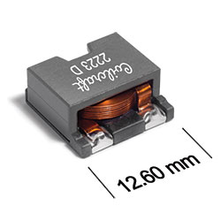
ST598PTA Series
Power Inductors for Critical Applications
ST598PTA Series features exceptionally high current carrying capability (up to 43 Amps) and very low DC resistance
- Magnetic shielding allows high density mounting; flat wire winding keeps the overall height to just 6 mm.
- Terminals 1 and 2: Tin-silver over tin over nickel over phos bronze; Terminal 3: Matte tin over nickel over phos bronze. Other terminations available at additional cost.
Specifications
Electrical specifications at 25°C.
| Part number 1 |
Inductance (µH)
2
(Tolerance: ±10%) |
DCR (mΩ) 3 | SRF (MHz) 4 | Isat (A) 5 | Irms (A) 6 | |||||
|---|---|---|---|---|---|---|---|---|---|---|
| typ | max | min | typ | 10% drop | 20% drop | 30% drop | 20°C rise | 40°C rise | ||
| ST598PTA331KLZ | 0.33 | 0.77 | 0.85 | 140 | 200 | 36.0 | 41.0 | 43.0 | 13.0 | 16.9 |
| ST598PTA651KLZ | 0.65 | 0.77 | 0.85 | 112 | 160 | 23.0 | 27.0 | 28.0 | 13.0 | 16.9 |
| ST598PTA102KLZ | 1.0 | 2.4 | 2.6 | 52.5 | 75.0 | 32.0 | 33.0 | 33.5 | 9.5 | 13.0 |
| ST598PTA182KLZ | 1.8 | 2.4 | 2.6 | 35.0 | 50.0 | 17.0 | 19.0 | 20.0 | 9.5 | 13.0 |
| ST598PTA272KLZ | 2.7 | 2.4 | 2.6 | 29.4 | 42.0 | 12.0 | 13.0 | 14.0 | 9.5 | 13.0 |
| ST598PTA402KLZ | 4.0 | 5.5 | 6.1 | 23.8 | 34.0 | 11.0 | 12.0 | 13.0 | 7.1 | 9.4 |
| ST598PTA472KLZ | 4.7 | 5.5 | 6.1 | 22.4 | 32.0 | 9.5 | 11.0 | 12.0 | 7.1 | 9.4 |
| ST598PTA602KLZ | 6.0 | 5.5 | 6.1 | 19.6 | 28.0 | 8.0 | 9.0 | 9.5 | 7.1 | 9.4 |
| ST598PTA802KLZ | 8.0 | 9.8 | 10.8 | 18.2 | 26.0 | 7.5 | 8.5 | 9.0 | 5.5 | 7.6 |
| ST598PTA103KLZ | 10 | 9.8 | 10.8 | 16.8 | 24.0 | 6.2 | 7.0 | 7.5 | 4.4 | 7.2 |
| ST598PTA223KLZ | 22 | 9.8 | 10.8 | 9.1 | 13.0 | 2.4 | 3.0 | 3.3 | 4.4 | 7.2 |
Notes
- When ordering, please specify termination and screening codes: e.g. ST598PTA223KLZ.
- Inductance measured at 100 kHz, 0.1 Vrms, 0 Adc on an Agilent/HP 4284A or equivalent.
- DCR measured on a micro-ohmmeter.
- SRF measured using an Agilent/HP 8753D network analyzer.
- DC current at 25°C that causes the specified inductance drop from its value without current.
- Current that causes the specified temperature rise from 25°C ambient. This information is for reference only and does not represent absolute maximum ratings.
Termination:
- L =Terminals 1 and 2: Tin-silver over tin over nickel over phos bronze; Terminal 3: Matte tin over nickel over phos bronze.
- T = All terminals: copper (95.5/4/0.5) over tin over nickel over phos bronze. (Special order, added cost)
- S = All terminals: Tin-lead (63/37) over tin over nickel over phos bronze. (Special order, added cost)
Screening:
- Z = Unscreened
- Y = Unscreened (SLDC Option A)
- W = Unscreened (SLDC Option B)
- H = Coilcraft CP-SA-10001 Group A
- G = Coilcraft CP-SA-10001 Group A (SLDC Option A)
- D = Coilcraft CP-SA-10001 Group A (SLDC Option B)
Custom screening also available.
Environmental
Ambient temperature range:
–40°C to +85°C with Irms current.
Storage temperature range:
Component: –55°C to +125°C.
Tape and reel packaging: –40°C to +80°C.
Tape and reel packaging: –40°C to +80°C.
Maximum part temperature:
+125°C (ambient + temp rise).
Failures in Time (FIT) / Mean Time Between Failures (MTBF):
Performance curves
L vs Current

L vs Frequency

Temperature Rise vs Current


General specification
Core Material:
Ferrite
Weight:
2.3 – 3.2 g
Packaging:
500 per 13″ reel; Plastic tape: 24 mm wide, 0.4 mm thick, 16 mm pocket spacing, 6.6 mm pocket depth.
Soldering/Washing
Moisture Sensitivity Level (MSL):
1 (unlimited floor life at <30°C / 85% relative humidity).
Resistance to soldering heat:
Max three 40 second reflows at +260°C, parts cooled to room temperature between cycles.
Refer to Soldering Coilcraft Components before soldering.