3D Model
Datasheet
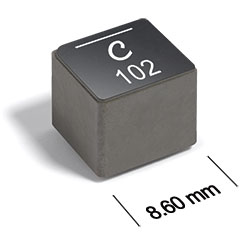
ST553PYA Series
High-Reliability Power Inductors
ST553PYA Series features high current and very low DCR.
- High current – up to 38 A
- Very low DCR – as low as 1.38 mOhms
- Soft saturation makes them ideal for VRM/VRD applications.
- Tin-silver (96.5/3.5) over copper terminations.
Specifications
Electrical specifications at 25°C.
| Part number 1 |
Inductance (µH)
2
(Tolerance: ±20%) |
DCR (mΩ) 3 | SRF typ (MHz) 4 | Isat (A) 5 | Irms (A) 6 | ||
|---|---|---|---|---|---|---|---|
| typ | max | 20°C rise | 40°C rise | ||||
| ST553PYA681MLZ | 0.68 | 1.4 | 1.7 | 70.0 | 38.0 | 20.3 | 27.8 |
| ST553PYA102MLZ | 1.0 | 2.1 | 2.3 | 49.2 | 31.3 | 18.7 | 25.6 |
| ST553PYA222MLZ | 2.2 | 4.1 | 4.5 | 36.7 | 24.0 | 12.0 | 16.1 |
| ST553PYA472MLZ | 4.7 | 8.9 | 9.8 | 24.1 | 17.4 | 7.9 | 10.9 |
| ST553PYA682MLZ | 6.8 | 13.2 | 14.5 | 20.6 | 14.0 | 6.0 | 8.5 |
| ST553PYA103MLZ | 10 | 21.0 | 23.1 | 15.6 | 10.9 | 4.9 | 6.5 |
| ST553PYA123MLZ | 12 | 16.4 | 18.2 | 11.3 | 8.6 | 5.7 | 7.9 |
| ST553PYA153MLZ | 15 | 20.3 | 22.5 | 10.5 | 7.7 | 5.2 | 7.1 |
| ST553PYA183MLZ | 18 | 25.2 | 28.0 | 9.1 | 6.6 | 4.5 | 6.2 |
| ST553PYA223MLZ | 22 | 29.6 | 32.9 | 8.2 | 6.4 | 4.2 | 5.7 |
| ST553PYA333MLZ | 33 | 43.7 | 48.5 | 6.8 | 5.0 | 3.3 | 4.5 |
| ST553PYA473MLZ | 47 | 64.7 | 71.8 | 5.9 | 4.4 | 2.6 | 3.6 |
Notes
- When ordering, please specify termination and screening codes: e.g. ST553PYA473MLZ.
- Inductance tested at 100 kHz, 0.1 Vrms using an Agilent/HP 4192A.
- DCR measured on a micro-ohmmeter.
- SRF measured using an Agilent/HP 4395A or equivalent.
- DC current at 25°C that causes a 30% (typ) inductance drop from its value without current.
- Current that causes the specified temperature rise from 25°C ambient. This information is for reference only and does not represent absolute maximum ratings.
Note:
Irms testing was performed on a 0.060″ thick pcb with 4 oz. copper traces optimized to minimize additional temperature rise. Temperature rise is highly dependent on many factors including pcb land pattern, trace size, and proximity to other components. Therefore temperature rise should be verified in application conditions.
Termination:
- L = Tin-silver (96.5/3.5) over copper.
- S = Tin-lead (63/37) over copper. (Special order, added cost)
Screening:
- Z = Unscreened
- Y = Unscreened (SLDC Option A)
- W = Unscreened (SLDC Option B)
- H = Group A screening per Coilcraft CP-SA-10001
- G= Coilcraft CP-SA-10001 Group A (SLDC Option A)
- D = Coilcraft CP-SA-10001 Group A (SLDC Option B)
Custom screening also available.
Environmental
Ambient temperature range:
–40°C to +125°C with Irms current.
Storage temperature range:
Component: –55°C to +165°C.
Tape and reel packaging: –55°C to +80°C.
Tape and reel packaging: –55°C to +80°C.
Maximum part temperature:
+165°C (ambient + temp rise).
Failures in Time (FIT) / Mean Time Between Failures (MTBF):
Performance curves
L vs Frequency

L vs Current


General specification
Core Material:
Composite
Weight:
3 g
Packaging:
450 per 7″reel Plastic tape: 24 mm wide, 0.3 mm thick, 16 mm pocket spacing, 8.36 mm pocket depth.
Soldering/Washing
Moisture Sensitivity Level (MSL):
1 (unlimited floor life at <30°C / 85% relative humidity)
Resistance to soldering heat:
Max three 40 second reflows at +260°C, parts cooled to room temperature between cycles.
Refer to Soldering Coilcraft Components before soldering.